This tutorial will continue from Tutorial 25, where we implemented a noise function. Now that you have the Perlin Noise-function in your shader, it is very simple to implement Bump Mapping.
The object being rendered contains normals on each point of the surface. By calculating the gradient vector for each normal, you can modify the normal to point in a slightly different direction, based on the “bumps” the noise function creates, to create the illusion of a bumpy surface. The Normal must be modified so it point in the right direction based on the bumps, are we going “up” on the side of the bump? Or are we going “down”?
The algorithm
Say you have a function F(x,y,z) that produce a noise based pattern, as inoise() from tutorial 25. By slightly modifying the input of this function, you can calculate the gradient vector. We create a new variable E (EPSILON) that contains a small value like 0.001f. We then use E with the point P as input to the function F for each X, Y and Z:
Fx, Fy and Fz can now be used to calculate the gradient vector:
Now you got the gradient vector, and can calculate the new vector by subtracting this from the original Normal.
After that, you can implement the lighting model you want the normal way. In this tutorial, we simply use the diffuse lighting model from Tutorial 2.
Where N.L is the dotprocut between the Normal vector N and the light vector L.
The implementation
You can implement the whole bump mapping algorithm in the shader. We start by implementing the light algorithm in the vertex shader, shouldn’t be new to you:
struct VertexShaderInput { float4 Position : POSITION0; float2 texCoord : TEXCOORD0; float3 Normal : NORMAL; };
Next, we create Fx,Fy and Fz by using the exact same function F used to produce the color, but instead of using point P, we use the E-modified point Px, Py and Pz:
float3 bump = float3( inoise(pX)*0.5+0.5,inoise(pY)*0.5+0.5,inoise(pZ)*0.5+0.5); float3 modNormal = float3( (bump.x-inz) / E, (bump.y-inz) / E, (bump.z-inz) / E);
We then subtract the gradient vector from the input Normal, and normalize this: float3 Normal = normalize(input.Normal – modNormal);
All that is left is to implement the lighting model we want (in this case, diffuse light), using the new modified Normal:
float Ai = 0.3f; float4 Ac = float4(0.3, 0.0, 0.3, 1.0); float Di = 1.0f; float4 Dc = float4(1.0, 1.0, 1.0, 1.0); return Ai*Ac + color*saturate(dot(input.Light, Normal)); }
That is all there is to bump mapping your noise function.
This tutorial will intruduce you to procedural textures. If you ever want to generate textures procedurally, you probably stumble upon the Perlin Noise algorithm created by Ken Perlin in 1983.
Why noise?
If you are trying to model natural textures like grass, grain, wood, marble, clouds (+++), you want the textures to contain some irregularity to avoid making the texture look too repeating or perfect. This can be done by using pseudo-random numbers (PRN). You also want to have control over the PRN when using them in your texture generators, so your output won’t be different every time you run your program, or every frame.
Perlin Noise does this. It’s an algorithm that generates a real PRN for every point in space in the range –1 to 1, and it’s controllable (if you know the seed that generates the pattern you want, you can get the same pattern later). The values that the Perlin Noise function returns changes smoothly when moving from a point P1 to another point P2.
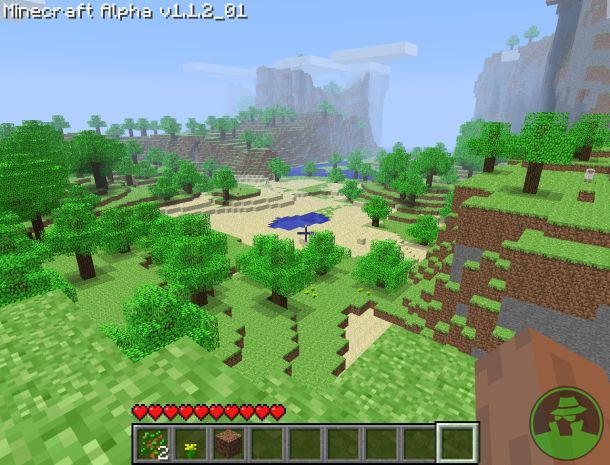
Perlin Noise can be used in many other situations as well, like generating landscapes (Minecraft is using this to generate the landscape), fractals, vertex displacements and so on. It’s also used in movies like Tron, LOTR and A Perfect Storm.
Ken Perlin himself has written an article on generating Perlin Noise on the GPU. This article can be found in the book GPU Gems 1, and another one in GPU Gems 2. You can read them for free online here:
The algorithm can be learned from the presentation “Making Noise” by Ken Perlin at GDCHardCore on Dec 9, 1999.
Noise can be used in any space Rn. You input a coordinate, and it returns a PRN-value for that coordinate. The Noise function is defined on a regular grid, where each grid point is a whole number.
When you feed the input coordinate, the algorithm will look at each of the surrounding 2n grid points. The grid points are located on the grid corners (whole numbers), and the point P is the fraction, somewhere between the grid points.
At each surrounding grid point, you select a “random” gradient vector. The same gradient vector must be used for the same grid-point every time, and have the length of 1.
Also, we need the vectors from each grid point to point P, let’s call them gP:
By performing the dot product on the gradient vectors and gP, we can find out how much each of them is affecting point P.
Then you interpolate between all of the values computed above to get the final value for point P. If you are in 3D space R3, you will have 8 surrounding grid points, and 7 interpolations to get the final value.
The first thing that we need is a pre-computed table containing the values 0 – 255 in random order, in two dimensions. This is used to generate one or more PRN at every point P.
We also need a table of gradients. We are implementing noise over R4, and thus needs 16 gradients points.
These will have to be generated on the CPU during loading, as it’s not possible to do it on the GPU with XNA. Also, as these are arrays, and XNA doesn’t support arrays in the shaders, we pass them to our shader as textures.
The shader then use these textures to calculate noise.
Implementaion
First, we create the lookup table for the permutations, and the gradients. Start by creating a new class named PerlinNoise and define it as the following:
using System; using System.Collections.Generic; using System.Linq; using System.Text; using Microsoft.Xna.Framework.Graphics; using Microsoft.Xna.Framework; using Microsoft.Xna.Framework.Graphics.PackedVector;
namespace NoiseGPU { public class PerlinNoise { GraphicsDevice device;
public PerlinNoise() { } } }
Then we define our two tables as local variables to the class:
// permutation table static int[] permutation = new int[256];
Notice that the permutation table is empty. We calculate this in a function named InitNoiseFunction(int seed). This function takes in a seed (so we can get the same result next time we run the application), and generates our permutations.
public void InitNoiseFunctions(int seed, GraphicsDevice device) { this.device = device;
Random rand = new Random(seed);
// Reset for (int i = 0; i < permutation.Length; i++) { permutation[i] = -1; }
// Generate random numbers for (int i = 0; i < permutation.Length; i++) { while (true) { int iP = rand.Next() % permutation.Length; if (permutation[iP] == -1) { permutation[iP] = i; break; } } } }
Now that we got our two tables ready, we can start creating our textures so we can pass the tables in to our shader:
public Texture2D GeneratePermTexture2d() { Texture2D permTexture2d = new Texture2D(device, 256, 256, true, SurfaceFormat.Color); Color[] data = new Color[256 * 256]; for (int x = 0; x < 256; x++) { for (int y = 0; y < 256; y++) { int A = perm2d(x) + y; int AA = perm2d(A); int AB = perm2d(A + 1); int B = perm2d(x + 1) + y; int BA = perm2d(B); int BB = perm2d(B + 1); data[x + (y * 256)] = new Color((byte)(AA), (byte)(AB), (byte)(BA), (byte)(BB)); } } permTexture2d.SetData<Color>(data); return permTexture2d; }
public Texture2D GeneratePermGradTexture() { Texture2D permGradTexture = new Texture2D(device, 256, 1, true, SurfaceFormat.NormalizedByte4); NormalizedByte4[] data = new NormalizedByte4[256 * 1]; for (int x = 0; x < 256; x++) { for (int y = 0; y < 1; y++) { data[x + (y * 256)] = new NormalizedByte4(gradients[permutation[x] % 16, 0], gradients[permutation[x] % 16, 1], gradients[permutation[x] % 16, 2], 1); } } permGradTexture.SetData<NormalizedByte4>(data); return permGradTexture; }
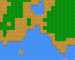
These two functions simply maps the tables into two textures. The first one generates a 2d table of 256×256 PRN values, and returns an output similar to the image below:
The other functions takes the gradients from our array, and store the directions as colors into a 16×1 sized texture. Its output is similar to the image below:
Now, over to our shader. I added a new Effect file to the project and changed the vertex shader to look like this:
It’s out of the box with two exceptions, the texture coordinate and a new variable named wPosition, simply the world position of the vertex. This will be used as the input point P to our noise algorithm (the point P we talked about in the theory section).
Next, we need our two textures and their samplers:
gradperm compute the inner product of the gradient vector, and the vector from the point P to the grid-coordinate.
Then we create the algorithm itself.
float inoise(float3 p) { float3 P = fmod(floor(p), 256.0); // FIND UNIT CUBE THAT CONTAINS POINT p -= floor(p); // FIND RELATIVE X,Y,Z OF POINT IN CUBE. float3 f = fade(p); // COMPUTE FADE CURVES FOR EACH OF X,Y,Z.
P = P / 256.0; const float one = 1.0 / 256.0;
// HASH COORDINATES OF THE 8 CUBE CORNERS float4 AA = perm2d(P.xy) + P.z;
// AND ADD BLENDED RESULTS FROM 8 CORNERS OF CUBE return lerp( lerp( lerp( gradperm(AA.x, p ), gradperm(AA.z, p + float3(-1, 0, 0) ), f.x), lerp( gradperm(AA.y, p + float3(0, -1, 0) ), gradperm(AA.w, p + float3(-1, -1, 0) ), f.x), f.y),
lerp( lerp( gradperm(AA.x+one, p + float3(0, 0, -1) ), gradperm(AA.z+one, p + float3(-1, 0, -1) ), f.x), lerp( gradperm(AA.y+one, p + float3(0, -1, -1) ), gradperm(AA.w+one, p + float3(-1, -1, -1) ), f.x), f.y), f.z); }
This functions puts it all together. It first makes a unit cube around the point and the coordinates of the cube. It then computes the face curves for each axis of the point. Then we interpolate
The only thing that needs an explanation here is the inx variable. As the noise is in the –1 to 1 scale, we need to change this in to a 0 to 1 scale. It’s done by multiplying the value with 0.5 and adding 0.5 to it.
Implementing our application
Now, let’s take this into use. Nothing should be new in this code.
using System; using System.Collections.Generic; using System.Linq; using Microsoft.Xna.Framework; using Microsoft.Xna.Framework.Audio; using Microsoft.Xna.Framework.Content; using Microsoft.Xna.Framework.GamerServices; using Microsoft.Xna.Framework.Graphics; using Microsoft.Xna.Framework.Input; using Microsoft.Xna.Framework.Media; using Microsoft.Xna.Framework.Graphics.PackedVector;
namespace NoiseGPU { /// <summary> /// This is the main type for your game /// </summary> public class Game1 : Microsoft.Xna.Framework.Game { GraphicsDeviceManager graphics; SpriteBatch spriteBatch; Model meshObject; Matrix projection, view; Effect perlinNoiseEffect;
public Game1() { graphics = new GraphicsDeviceManager(this); Content.RootDirectory = “Content”; }
/// <summary> /// Allows the game to perform any initialization it needs to before starting to run. /// This is where it can query for any required services and load any non-graphic /// related content. Calling base.Initialize will enumerate through any components /// and initialize them as well. /// </summary> protected override void Initialize() { float aspectRatio = graphics.GraphicsDevice.Viewport.AspectRatio; projection = Matrix.CreatePerspectiveFieldOfView(MathHelper.ToRadians(45.0f), aspectRatio, 1.0f, 10000.0f);
/// <summary> /// LoadContent will be called once per game and is the place to load /// all of your content. /// </summary> protected override void LoadContent() { // Create a new SpriteBatch, which can be used to draw textures. spriteBatch = new SpriteBatch(GraphicsDevice); meshObject = Content.Load<Model>(“sphere”); perlinNoiseEffect = Content.Load<Effect>(“perlinNoiseEffect”);
foreach (ModelMesh mesh in meshObject.Meshes) { foreach (ModelMeshPart part in mesh.MeshParts) { part.Effect = perlinNoiseEffect; } }
// TODO: use this.Content to load your game content here }
/// <summary> /// UnloadContent will be called once per game and is the place to unload /// all content. /// </summary> protected override void UnloadContent() { // TODO: Unload any non ContentManager content here }
/// <summary> /// Allows the game to run logic such as updating the world, /// checking for collisions, gathering input, and playing audio. /// </summary> /// <param name=”gameTime”>Provides a snapshot of timing values.</param> double timer = 0; protected override void Update(GameTime gameTime) { timer += gameTime.ElapsedGameTime.Milliseconds/5000.0; // Allows the game to exit if (GamePad.GetState(PlayerIndex.One).Buttons.Back == ButtonState.Pressed) this.Exit();
/// <summary> /// This is called when the game should draw itself. /// </summary> /// <param name=”gameTime”>Provides a snapshot of timing values.</param> protected override void Draw(GameTime gameTime) { GraphicsDevice.Clear(Color.DarkOliveGreen);
DrawModel(meshObject, projection, view);
spriteBatch.Begin(SpriteSortMode.Deferred, new BlendState()); spriteBatch.Draw(permGradTexture, new Rectangle(0, 0, 256, 32), Color.White); spriteBatch.Draw(permTexture2d, new Rectangle(GraphicsDevice.Viewport.Width-256, 0, 256, 256), Color.White); spriteBatch.End();
base.Draw(gameTime); } } }
We render a sphere using the noise effect we created, and also render the two textures we are generating.
Update: All needed files for this tutorial can be found in the GitHub repo linked in the bottom of this page.
We are not going to introduce many new things in this tutorial, just use what you know to create more than one interrupt. Interrupts can be used to split you screen into different sections.
An important note is that these “interrupts” is your bridge to how it will be done when you get to a more advanced level (will be covered in a later part) and is intended for beginners. These will get you going, but know that there is a better and more correct way to do interrupts. In how I teach, I find it easier to start this way and then move to the correct way when the basic understanding is in place.
Anyways, say you want one part of your screen to render an image, and then once the image is rendered, you want to render some text. That means that you must set up your screen to support both graphic mode and text mode. This can be done with interrupts!
I’m going to create a program that splits the screen into two, where the first part got a purple color and the second part got a green color. We split the screen on every refresh using two interrupts.
The first interrupt does some logic before changing the IRQ vector to point to another “IRQ function” before returning to the main loop. The other interrupt does some logic, triggers another raster interrupt, changes the IRQ vector back to the original and returns to the main loop.
Not much is changed since the previous tutorial. We start with the exact same logic until the main loop starts to run:
processor 6502
org $0810
; initiate music lda #$00 tax tay jsr $1000
;clear screen
jsr $e544
; disable interrupts
sei
lda #$7f
sta $dc0d
sta $dd0d
lda #$01
sta $d01a
; set text mode
lda #$1b
ldx #$08
ldy #$14
sta $d011
stx $d016
sty $d018
; clear interrupts and ACK irq
lda $dc0d
lda $dd0d
asl $d019
cli
loop: jmp loop
In the first irq, we set the color of the border and mainscreen, updates the music..
irq: lda #$04
sta $d020
sta $d021
jsr $1006
..and then use the same logic as earlier to set the IRQ vector to point to irq2.
lda #<irq2
ldx #>irq2
sta $0314
stx $0315
We set the next raster interrupt at line 160:
ldy #160
sty $d012
asl $d019
jmp $ea81
The code for the 2nd interrupt is very similar to the first one. We set the color of the border and the screen, and then set the IRQ-vector to point on irq.
irq2:
lda #$05
sta $d020
sta $d021
lda #<irq
ldx #>irq
sta $0314
stx $0315
ldy #$00
sty $d012
asl $d019
jmp $ea81
Finally, we set the music at location $1000-7e:
org $1000-$7e
INCBIN “music.sid”
As I said, nothing new here really. Interrups are really handy when it comes to splitting the screen and timing. One thing to remember is that these interrups are not stable, so you might see some jittering or artifacts on the screen. It’s all about timing. We are going to see how to create stable interrupts in a later tutorial.
Note: You are not limited to only have two interrupts. Feel free to play around a bit, make some lines and so on.
An excerise for you:
Try to see if you can get the position of the split to move up and down. It might not be as easy as you thing, but you should be able to do this by now!
Listing 10.1 – More than one interrupt
processor 6502
org $0810
; initiate music lda #$00 tax tay jsr $1000
;clear screen
jsr $e544
; disable interrupts
sei
lda #$7f
sta $dc0d
sta $dd0d
lda #$01
sta $d01a
; set text mode
lda #$1b
ldx #$08
ldy #$14
sta $d011
stx $d016
sty $d018
Update: All needed files for this tutorial can be found in the GitHub repo linked in the bottom of this page.
In this tutorial we will take a look at one of the most important topic when it comes to C-64 programming – Interrupts.
Interrupts are used to pause whatever the machine is doing at a given condition, and do another task. When the interrupt is complete, your program will continue to run where it was interrupted.
An interrupt might be a timer interrupt that happens when a given amount of cycles has passed, a raster interrupt, a collision interrupt and so on. You can have multiple interrupts during a screen refresh. If you have interrupts enabled, and don’t use them to time your program, your application will be jerky and flickering.
There are two types if interrupts. One is Interrupt Request (IRQ), the one we are going to program in this tutorial, and then another one named Non-Maskable Interrupt (NMI). The difference between these is only that you can turn off the IRQ’s, but not the NMI’s (unless you do a trick).
We are also going to introduce two new instructions, SEI and CLI:
– SEI (SEt I(nterrupt) flag) instruction does disable interrupts.
– CLI (CLear I(nterrupt) flag) instruction does enable interrupts.
There is an initialization process when creating interrupts. During this, it’s very important to disable interrupts just to make sure another interrupt won’t ruin the init process. (If not, your application MIGHT crash)
The example in this tutorial will use interrupts to play music. Playing music in a program is very simple. Only a music file (.sid) and 5 lines of code is required. You also need to find some numbers that will be used to locate, init and play the music using a SID-player tool.
You can create your own music, but since I’m nothing near a musician, I downloaded a music and used this in our example. The file is named music.sid, and the title of the song is “Masses Zak”. I got the file from High Voltage SID Collection, a page with a huge archive of C-64 music. Be sure to take a look!
You also need a tool that can play music files, just to find out some information about the file, like where in the memory it will be stored. Most files will be at $1000, but not all.
The SID player I use is named Sidplay2 for Windows and can be downloaded here.
Now, download and start Sidplay 2, open “music.sid” (can be downloaded above) and the music will start playing. Now click File->Properties to see a long list with information regarding the SID-file:
What’s important to note is the Load range, Init address and Play address. These will be used when we init and play our song (d’Oh).
Let the programming begin!
As usual, we start by telling the compiler what processor we are programming for, and where in the memory our program should start.
processor 6502
org $0810
But wait, we are starting on $0810 instead of $1000? Why is this? Well, our music file will be loaded into $1000 (Load range), so we simply move the start address for our program to $0810. To run our program, start it in the emulator and write SYS 2064 (decimal of 0810 hex)
Next we initiate the music. This is done but putting the value 00 into the x- and y-registers, and call the subroutine that resets the SID-chip. The properties in the SID file stated that the init routine for the music is at $1000, so that’s what we want to do.
lda #$00
tax
tay
jsr $1000
Now we are going to initiate the interrupts. First we need to turn off the interrupts: sei
Then we put the value 7f into $dc0d and $dd0d to disable the CIA I, CIA II and VIC interrupts (timer, keyboard,…, interrupts) lda #$7f
sta $dc0d
sta $dd0d
We also need to enable raster interrupts. We do this by inserting 01 into $d01a. lda #$01
sta $d01a
Next we tell the VIC that we want to enter single-color text mode. Inserting 1b into $d011 means “Enter text-mode”, and inserting 08 into $d016 means “Use single-color”. We also tell the VIC that our screen RAM is at $0400 and that we want to use the default charset by inserting 14 into $d018 (see earlier tutorials for more information about how this works). lda #$1b
ldx #$08
ldy #$14
sta $d011
stx $d016
sty $d018
Now we are at the meat of this tutorial. What we will do next is to load the interrupt handlers codes lower and high part into the interrupt vector at $0314-$0315. “irq” is the label where the code for our interrupt is located, so all we do is to insert a pointer to this into $0314-$0315: lda #<irq
ldx #>irq
sta $0314
stx $0315
Then we need to create the trigger for out interrupt at “irq”. We want a raster interrupt at any line (in this example $7e) to trigger the interrupt. ldy #$7e
sty $d012
Then we clear pending interrupts (the CIA 1, CIA 2 and VIC interrupts). lda $dc0d
lda $dd0d
asl $d019
Now that the interrupt is initiated, we can enable interrupts and start with the program logic. In this example, we are only running an infinite loop: cli loop: jmp loop ; infinite loop
Next is the code for our interrupt. What this does is to first run a sub routine at $1006 (the play SID-file routine for music.sid (remember the properties of the sid file)): irq: jsr $1006
Then we ACK the interrupt with asl $d019. This is done because we don’t want the interrupt to be called again right after we return from it. asl $d019
Then we jump to a subroutine that restores the stack and returns from the interrupt. If you want to save 3 cycles, you could write this manually, but for simplicity, we jump to $ea81 (see below for what you can replace this with if you want to write the code yourself): jmp $ea81
The last thing we do is loading the music into $1000. But a SID file got an offset of $7e so we need to subtract this from $1000 so the file is correctly placed in memory.
org $1000-$7e
INCBIN “music.sid”
That’s if for basic interrupt. We will be more advanced in a later tutorial as interrupts are really important when it comes to C-64 programming.
A complete listing of our example is in listing 9.1.
Listing 9.1 – Interrupts and music
processor 6502
org $0810
lda #$00
tax
tay
jsr $1000
sei
lda #$7f
sta $dc0d
sta $dd0d
lda #$01
sta $d01a
lda #$1b
ldx #$08
ldy #$14
sta $d011
stx $d016
sty $d018
lda #<irq
ldx #>irq
ldy #$7e
sta $0314
stx $0315
sty $d012
lda $dc0d
lda $dd0d
asl $d019
cli
loop: jmp loop
irq: jsr $1006
asl $d019
jmp $ea81
Update: All needed files for this tutorial can be found in the GitHub repo linked in the bottom of this page.
In the previous tutorial, we learned how to create and render a bitmap, and how to enter bitmap-mode.
In this tutorial, we are going to use almost the same concepts, but instead of rendering bitmaps, we are rendering text. We are also going to use a custom charset instead of the pretty boring charset that’s default.
The default charset look like this:
First of all, I’m not good at creating fonts so I won’t teach you how to do this. Instead we are going to download a charset that is named Scrap Writer III 17. Don’t know who created it but if anyone knows, please let me know so I can add proper credits.
Download other charsets from this page: http://kofler.dot.at/c64/ but remember, some of them might be copyrighted.
Rendering text
Rendering text is quite simple. All you need is to either use the default charset or a custom charset. Also, you will need the text you want to render.
Let’s write our program.
First, we want to clear the screen. You could use the method we created earlier, but to keep this example to the point, I’m going to use a function that is included on the Commodore 64 and located at $e544. This routine clears the screen.
Also, we want to set the screen color and the border color to something greenish.
processor 6502
org $1000
jsr $e544
lda #$0d
sta $d020
lda #$05
sta $d021
Then we load the custom charset, using the same method as in the previous tutorial about rendering bitmaps. Our screen memory is at $0400 and charset at $2000. lda #$18
sta $d018
Now it’s time for the meat of this tutorial. The loop that writes the text! First, we set the x-register to zero. Then we load the x’th character of msg (declared in the bottom) into the accumulator.
ldx #$00
write: lda msg,x
Once it’s loaded, we jump to a subroutine that writes text to the screen. This routine is located at $ffd2. All it does is to write the value in the accumulator to the screen. jsr $ffd2
The text we want to render is 54 character long. We loop through each of the characters and write it to the screen. inx
cpx #54
bne write
Next we are setting the color of our characters. This could be done in the loop above, but just to split the different functionality, I decided to create another loop that does this. The color is stored at $d800 and so on. We do this for each of the 54 characters.
Update: All needed files for this tutorial can be found in the GitHub repo linked in the bottom of this page.
In this tutorial we are going to cover two things. First we will look at one way of creating bitmaps/images for our C-64 programs by using a tool for Windows. Next we will load the image we created into our own program and render it.
Creating bitmaps
Before you can draw your bitmap, you will need a tool. The tool I like to use is named Timanthes v3, and can be downloaded below.
Load Timanthes and you will see an environment much similar to other painting programs in front of you. When painting for the Commodore 64 you must be aware of a few limitations. The Commodore 64 supports a few different graphic modes. The one introduced here is a pretty common one and will work as a basis to understand the rest of them.
The format we are implementing is named MultiColor and got a resolution of 160×200 pixels, with the support of 16 colors. As you can see, the resolution of the images is smaller than the screen. One pixel in the image represents 2×1 pixels when rendered on the screen. Another important attribute with this mode is that the screen is divided into 40×25 attribute cells, where each attribute cell is 4×8 pixels in size. Each is also limited to contain the maximum of 4 colors.
Confused? Let me break it down for you:
The image is 160×200 in size…
..where one pixel in the image represents 2×1 pixels in screen size: In this picture, I drew ONE line across 8 pixels, and another line down 8 pixels. Notice that the width of one pixel spans across two pixels when rendered.
I also mentioned that this image mode splits the image into 40×25 attribute cells:
where each of the cells contains 4×8 pixels (8×8 in real): This is one cell. It contains 4 pixels you can draw in the x-axis and then 8 pixels you can draw in the y-axis. One pixel in the x-axis represents 2 pixels in screen size.
Also, one cell can only contain the maximum of 4 colors, including the background. If you try to draw more than 4 colors in Timanthes, a red pixel will show on the colors that exceed the limit, and must be corrected.
Now, the first thing you will see when loading Timanthes is that you got a drawing area and some floating windows. Move these into a position you like. Now, in the layers window, notice that you got two layers. This is how it should be when exporting your image to a prg file. You NEED to have two layers. I usually draw on the 2nd layer.
Also, on the right side of the layer preview image, you can see what type of layer your dealing with:
This is where you select what kind of graphic mode you want the image in. Select Layer 2 (it’s probably already selected) and click the properties button:
You will see a popup window:
In Mode, select “Bitmap multicolor” and click OK.
Now, select a color from the Colors window. This is the palette. This mode support 16 different colors. You can modify each color from this window. But remember, 16 in total is the limit.
Now, draw any image. My result was this, the logo of my group in the demoscene. You can download the file below.
Now it’s time to export your image from Timanthes. Click File and Export As, the type must be .PRG and you can name it whatever you want. I named mine dcc.prg. Press OK and a new popup will show:
You can leave it like this for this example, but these values are the values we are going to use when loading the image into memory and displaying it!
Keep in mind that one image takes about 2000 bytes in memory, so it has to be loaded into $2000, $4000, $6000 and so on, and not in $2456.
Let’s write our code. A complete listing can be seen below.
First of all, we set the background color to the one that the image is using. When you exported the image, you noticed that the background is stored in $4710. Load the value from here into the d020 and d021 memory.
processor 6502
org $1000
lda $4710
sta $d020
sta $d021
Now we will create a loop that copies the data to screen RAM that starts at $0400. The data (in one way, we use characters (the cells), but more on this later) for our image is located at $3f40 (as we noticed when we exported the image). We use the same method for copying as in the earlier example where we cleared the screen.
First, set the x-register to zero, and start the copying:
ldx #$00
loaddccimage:
lda $3f40,x
sta $0400,x
lda $4040,x
sta $0500,x
lda $4140,x
sta $0600,x
lda $4240,x
sta $0700,x
Also, we must copy the color RAM for our image located at $4328 (specified when exporting the image) to $d800. We add this to the loop:
lda $4328,x
sta $d800,x
lda $4428,x
sta $d900,x
lda $4528,x
sta $da00,x
lda $4628,x
sta $db00,x
One last thing has to be done in the loop, and that is to increase x. If x does not equal zero, branch to the loaddccimage label.
inx
bne loaddccimage
The loop will now loop until x is zero, copying all data into the correct memory. Once this is done, the image is loaded and ready to display!
The next thing we need to do is to tell “the system” that we want to enter bitmap mode, and that the mode is a multicolor mode.
$d011 must be set to what mode we want to go into. To got into bitmap mode, we set $d011 to 3b:
lda #$3b
sta $d011
Now we are in bitmap mode.
Next, we must turn on multicolor-mode. This is done by putting the value in $d016 to 18.
lda #$18
sta $d016
Now, we are in bitmap multicolor-mode!
The last thing we need to do is to tell the VIC that the screen RAM is at 0400 and that the bitmap is at $2000. If we put in the value 18, the first numer (1) is where we want the screen RAM, and the last numer is where the bitmap is. How does this work? First, we know that out screen RAM is located at 0400 and is 0400 bytes long. We count how many times we need to “add” 400 bytes to reach to the desired screen RAM from 0000. So, 0000+0400 = 0400. Thats one time. Next, we must count how many times until we reach 2000. Thats 8 times. To set that the screen RAM is at 0400 and the bitmap is at 2000, we $d018 to #$18:
lda #$18
sta $d018
This might sound confusing. The screen memory is 400 bytes long, so it has to start on a memory address that is a multiple of 400. If you don’t change where the screen memory is, it’s located at $0400 by default like in this example.
Now, let’s add an infinite loop so that our program won’t just exit once the image is rendered:
loop:
jmp loop
That’s it for loading the image. One final thing remains, and that is to include our image file and put it into the memory. When we exported, we specified that we wanted to have the image at the memory location $2000. Now, a PRG file got a header that is 2 bytes long. That means that we want to include the file in location $2000-2 bytes = $1FFE:
org $1FFE
INCBIN “dcc.PRG”
If you compile and run this, the emulator will display the image as seen below.
A complete listing of our code can be found in listing 7-1.
Listing 7.1 – Complete listing for rendering your multicolor image
processor 6502
org $1000
lda $4710
sta $d020
sta $d021
ldx #$00
loaddccimage:
lda $3f40,x
sta $0400,x
lda $4040,x
sta $0500,x
lda $4140,x
sta $0600,x
lda $4240,x
sta $0700,x
lda $4328,x
sta $d800,x
lda $4428,x
sta $d900,x
lda $4528,x
sta $da00,x
lda $4628,x
sta $db00,x
inx
bne loaddccimage
lda #$3b
sta $d011
lda #$18
sta $d016
lda #$18
sta $d018
Update: All needed files for this tutorial can be found in the GitHub repo linked in the bottom of this page.
A raster line is the line that is being redrawn on the screen. You can create a lot of cool effects and implement smart logic that happens when the video signal reaches a specific raster line of your choice.
The screen is redrawn 50 times per second, from top to bottom, from the left to the right. This can be used to synchronize your logic with the screen refresh (and also with the clock!).
The current raster line is stored in the memory location $d012.
Let’s go back to our example in tutorial #1 where we changed the background color on the main area, using the following code:
processor 6502
org $1000
loop: inc $d021
jmp loop
This resulted in something similar to the screen below:
Now, let’s implement the same example, but synced with the screen refresh. The code is really short, so I’ll just give you the complete listing.
What this code does is to first load the value of d012 into the accumulator. And we check if it equals the value of ff (could be anything you want really).
Note: The screen size goes from 0 – 319, and the byte in d012 only got the range of 0 – 255. To get the rest of the screen, you can use the high bit in d011. If this is set, the value in d012 will contain the raster lines after 255. In other words, d011 is the 8th bit of d012.
Now, if you run the code above, you will get a screen that flashes different colors 50 times per second, without the color distortion that is created due to interrupts and timing.
Raster interrupts covered in tutorial 10 is a really important topic. It can be used to create a lot of cool effects like rendering more than 8 hardware sprites, split your screen into sections (one displaying hiQ graphics, other part displaying a font) and so on.
Update: All needed files for this tutorial can be found in the GitHub repo linked in the bottom of this page.
In the previous tutorials we created stuff that rendered a sprite and changed the color on things. In this tutorial, we will clear the screen to a black color.
To clear the screen, we should set the color of the border and the main screen to a given color, like black, and then we must clear the characters on the screen. This can be done by setting them to the character SPACE.
To do this, first we put the index for black into the accumulator, and store this into the border and the main screen.
processor 6502
org $1000
lda #$00
sta $d020
sta $d021
Next we copy the value in the accumulator into the x-register. tax
Then we put the value of #$20 in to the accumulator. #$20 is the value of the SPACE character. lda #$20
Now we are ready to put the value inserted in the accumulator into every character on the screen memory. This will be done by creating a loop that goes through the entire screen memory. The screen memory is located at $0400 and ends at $07FF.
Linus Åkerlund of Fairlight shared a smart way of looping through the screen memory. Before the loop starts, x contains the value 0. If we decrement it, it will become FF (255), and then go all the way down to 0 again, setting all the characters to space in the range 0400-04FF, 0500-05FF, 0600-06FF and 0700 to 07FF.
loop: sta $0400,x
sta $0500,x
sta $0600,x
sta $0700,x
dex
bne loop
The last instruction is new; bne will jump (branch) to loop if X is not zero. That means that when we start, X will be 0, and right before the bne operation, we will decrease it so it contains FF. This means that the loop will go all the way from FF to 00 before exiting the loop.
Listing 5.1 – Clear loop
processor 6502
org $1000
lda #$00
sta $d020
sta $d021
tax
lda #$20
loop: sta $0400,x
sta $0500,x
sta $0600,x
sta $0700,x
dex
bne loop
That’s it for clearing the screen. When the clear loop is done, you can continue doing what else you want the program to do.
Update: All needed files for this tutorial can be found in the GitHub repo linked in the bottom of this page.
In this tutorial we will take a quick look at how to render a sprite on the very nice standard C-64 background. Check out Sprite Pad for Windows to create sprites but for now, feel free to download the following sprite file: sprite1.prg
In the GitHub repo, there is another Sprite named sprite2.spr and the source in GitHub is using, as well as the SpritePad project file. Feel free to try both to see the difference.
Sprites are 2d images that you can move over a background, like a player character, a sun, a tree, an enemy and so on. You can have up to 8 sprites rendered at the same time.To render a sprite, you will have to enable it, give it a position, and have a pointer to its data.
Let’s do it step by step. First of all, we need to tell the compiler what processor we are writing our program for, and the entry point for it:
processor 6502
org $1000
Pointer to sprite data
Next, we need to create a pointer to our sprite data located at $2000 (you can put them in another location, but in this tutorial, we will put the data in $2000). The sprite pointers are the 8 bytes at the end of the screen memory (0400 – 0800):
Screen memory
Sprite 1
Sprite 2
Sprite 3
Sprite 4
Sprite 5
Sprite 6
Sprite 7
Sprite 8
0400 – 0800
07f8
07f9
07fa
07fb
07fc
07fd
07fe
07ff
One sprite takes 64 bytes of data, and 6410 (dec system) equals to 4016 (hex). If we set the pointer for sprite 1 (07f8) to #$00, the data for the sprite will be located at 0000. If we set it to #$01, the data will be located at 0040, if we set it to 2, the data will be located at 0080, if we set it to 3, it will be located at 00C0. How do I count this? 4016 * #number in pointer16 = where the memory for the sprite is located. Our sprite data will be located at $2000. So what value will we need to insert into 07f8? 4016 * 8016 = 200016, in other words, 8016.
We load the value 80 into A, and insert A into 07f8:
lda #$80
sta $07f8
Enable sprites
Next, we must turn on the sprite. You can use up to 8 sprites, and one byte FF equals 1111 1111, 8 bits. Each of these bits controls if a sprite is enabled or not, and is located in the $d015 block. We only want to enable sprite 1, so we set the first bit to 1 and the rest will remain 0.
This can be done in two ways, either by inserting the hex value, or the binary value. If you insert the hex value #$01, the result will be 0000 0001 and sprite 1 is enabled. If you insert #$02, the result in binary will be 0000 0010 and sprite 2 will be enabled. But if you insert #$03, the result will be 0000 0011, enabling both sprite 1 and 2!
You can also directly use the binary value by using #%0000001,#%0000010 and #%0000011.
We will use the hex value, and enable sprite 1: lda #$01
sta $d015
(Or like this if you want to use binary:
lda #%0000001
sta $d015 )
Set the XY position of the sprite
Next, we must set the XY-coordinates for our sprite. The coordinate memory is located from $d000. Both the X and the Y coordinate will need at least one byte each. To handle this, the first sprites X coordinate is located in $d000, and its Y coordinate is located at $d001. The 2nd sprites X coordinate is located at $d002, and its Y coordinate at $d003. The thirds X is at $d004, and Y at $d005, and so on. If we load the value #$80 into $d000 and $d001, the first sprite will be located at coordinate #$80,#$80 = 128,128 in pixels. lda #$80
sta $d000
sta $d001
The last thing we do is to actually load our sprite into the memory at $2000: * = $2000
INCBIN “sprite1.prg”
Now, what we did was to first set the pointer to the data for our sprite, then we enabled the sprite, then sat the coordinates, and in the end loaded the data for our sprite.
Listing 4.1 – Complete listing for sprite example.
processor 6502
org $1000
lda #$80
sta $07f8
lda #$01
sta $d015
lda #$80
sta $d000
sta $d001
loop: jmp loop
* = $2000
INCBIN “sprite1.prg”
If you take this application and compile it, you will see the result below:
..and don’t ask what that sprite is, I’m not a designer!
Is your sprite different? I changed it a bit, so it should now just be a P.
That’s the end of this tutorial.. or is it? Hey? How wide is the C-64 screen? 320. And how large is one byte? 255.. and? Well, if 255 is the max we can insert into the sprites X coordinate, how can we move it all across the screen? Hmm.. good question.
Moving a sprite across the 255 limit
The answer is pretty simple. At the memory location $d010, we got 8 more bits to set. If the first bit in $d010 is set to 1, the position of sprite 1s X coordinate is:
256 + the value in d000
And this is the same for all of the 8 sprites.
So there you have it, see you next time
Thank you for considering giving a small donation! Any donations is really apprechiated, and will go to creating more content and tutorials on this blog.