
XNA Shader Programming
Tutorial 4 – Normal mapping

Welcome back to the XNA Shader Programming series. I hope you enjoyed the last 3 tutorials, and have started to get a grip on shaders!
Last time we talked about Specular lighting, and how to implement this in our own engines. Today I’m going to take this to the next level, and implement Normal Mapping.
Last time we talked about Specular lighting, and how to implement this in our own engines. Today I’m going to take this to the next level, and implement Normal Mapping.
Before we start
In this tutorial, you will need some basic knowledge of shaderprogramming, vector math and matrix math. Also, the project is for XNA 3.0 and Visual Studio 2008.
In this tutorial, you will need some basic knowledge of shaderprogramming, vector math and matrix math. Also, the project is for XNA 3.0 and Visual Studio 2008.
Normal Mapping
Normal mapping is a way to make a low-poly object look like a high-poly objekt, without having to add more polygons to the model. We can make surfaces, like walls, look alot more detailes and realistic by using the technique in todays lesson.
Normal mapping is a way to make a low-poly object look like a high-poly objekt, without having to add more polygons to the model. We can make surfaces, like walls, look alot more detailes and realistic by using the technique in todays lesson.
A easy way to descibe normal mapping is that it is used to fake the existence of geometry.
To compute normal mapping, we will need two textures: one for the colormap, like a stone texture, and a normal map that describes the direction of a normal. Instead of calculating the Light by using Vertex normals, we calculate lighting by using the normals stored in the normal map.

Sounds easy, ey? Well, there is one more thing. In most Normal mapping techniques( like the one I’m describing today ), the the normals are stored in something that is called texture space coordinate system, or tangent space coordinate system,. Since the light vector is handled in object or world space, we need to transform the light vector into the same space as the normals in the normalmap.
Tangent space
To describe tangent space, take a look at this image:
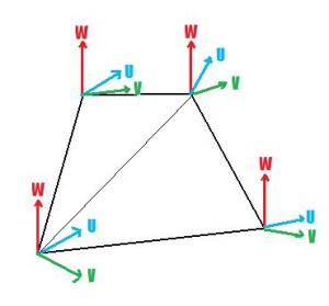
Our shader will create a vector W for the texture space coordinate system by using the normal. Then we will calculate U with the help of a DirectX Util function called D3DXComputeTangent() and then calculate vector V by taking the corss-product of W and U.
V = WxU.
To describe tangent space, take a look at this image:
Our shader will create a vector W for the texture space coordinate system by using the normal. Then we will calculate U with the help of a DirectX Util function called D3DXComputeTangent() and then calculate vector V by taking the corss-product of W and U.
V = WxU.
Lets take a closer look on how to implement this later, for now, let’s focus on todays next thing: Textures!
As you might have noticed, we need textures to implement normal mapping. Two textures to be spesific.
So, how do we load textures? In XNA this is very simple, and I’ll cover this later. And guess what? It’s just as simple to implement textures in our shaders.
To implement textures, we need to create something that is called Texture samplers. A texture sampler, as the name describes, sets the sampler state on a texture. This could be info about how the texture should use filtering( trilinear in our case ), and how the U,V coordinates of the texturemap will behave. This can be clamping the texture, mirroring the texture and so on.
To create a sampler for our texture, we first need to define a texture variable the sampler will use:
texture ColorMap;
We can now use ColorMap to create a texture sampler:
sampler ColorMapSampler = sampler_state
{
Texture = <ColorMap>; // sets our sampler to use ColorMap
MinFilter = Linear; // enabled trilinear filtering for this texture
MagFilter = Linear;
MipFilter = Linear;
AddressU = Clamp; // sets our texture to clamp
AddressV = Clamp;
};
{
Texture = <ColorMap>; // sets our sampler to use ColorMap
MinFilter = Linear; // enabled trilinear filtering for this texture
MagFilter = Linear;
MipFilter = Linear;
AddressU = Clamp; // sets our texture to clamp
AddressV = Clamp;
};
So, we got a texture and a sampler for this texture.
Before we can start using the texture in our shaders, we need to set a sampler stage in our technique:
Before we can start using the texture in our shaders, we need to set a sampler stage in our technique:
technique NormalMapping
{
pass P0
{
Sampler[0] = (ColorMapSampler);
{
pass P0
{
Sampler[0] = (ColorMapSampler);
VertexShader = compile vs_1_1 VS();
PixelShader = compile ps_2_0 PS();
}
}
PixelShader = compile ps_2_0 PS();
}
}
Ok, now we are ready to use our texture!
Since we are using a pixels shader to map a texture to an object, we can simply create a vector named color:
float4 Color;
float4 Color;
and set the values in the color variable to equal the color in our texture at texturecoordinate UV.
In HLSL, this can easily be done by using a HLSL function called tex2D( s, t ); where s is the sampler, and t is the texture coordinate of the pixel we are currently working on.
In HLSL, this can easily be done by using a HLSL function called tex2D( s, t ); where s is the sampler, and t is the texture coordinate of the pixel we are currently working on.
Color = tex2D( ColorMapSampler, Tex ); // Tex is an input to our pixel shader, from our vertex shader. It is the texture coordinate our PS is currently working on.
Texture coordinates?? Well, let me explain that. A texture coordinate is simpla a 2D coordinate ( U,V ) that is store in our 3D model or object. It is used to map a texture onto the object and are ranging from 0 to 1.
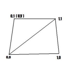
With texture coordinates, the model can have textures assigned to different places, say an Iris texture on the eyeball part of a human-model, or a mouth somewhere in a human face.
As for the lighting algortihm, we will use Specular lighting.
Ok, guess we are done with the teory, hope you got an overview of the different components needed in the Normal Map shader.
Implementing the shader
The biggest differences on this shader and the specular lighting shader is that we will use tangent space instead of object space, and that the normals used for lighting calculation will be retrived from a normal map.
The biggest differences on this shader and the specular lighting shader is that we will use tangent space instead of object space, and that the normals used for lighting calculation will be retrived from a normal map.
First of all, we need to create a new vertex definition that contains Tanges. Add the following piece of code in the top, inside the namespace:
public struct VertexPositionNormalTextureTangentBinormal
{
public Vector3 Position;
public Vector3 Normal;
public Vector2 TextureCoordinate;
public Vector3 Tangent;
public Vector3 Binormal;
public struct VertexPositionNormalTextureTangentBinormal
{
public Vector3 Position;
public Vector3 Normal;
public Vector2 TextureCoordinate;
public Vector3 Tangent;
public Vector3 Binormal;
public static readonly VertexElement[] VertexElements =
new VertexElement[]
{
new VertexElement(0, 0, VertexElementFormat.Vector3, VertexElementMethod.Default, VertexElementUsage.Position, 0),
new VertexElement(0, sizeof(float) * 3, VertexElementFormat.Vector3, VertexElementMethod.Default, VertexElementUsage.Normal, 0),
new VertexElement(0, sizeof(float) * 6, VertexElementFormat.Vector2, VertexElementMethod.Default, VertexElementUsage.TextureCoordinate, 0),
new VertexElement(0, sizeof(float) * 8, VertexElementFormat.Vector3, VertexElementMethod.Default, VertexElementUsage.Tangent, 0),
new VertexElement(0, sizeof(float) * 11, VertexElementFormat.Vector3, VertexElementMethod.Default, VertexElementUsage.Binormal, 0),
};
public VertexPositionNormalTextureTangentBinormal(Vector3 position, Vector3 normal, Vector2 textureCoordinate, Vector3 tangent, Vector3 binormal)
{
Position = position;
Normal = normal;
TextureCoordinate = textureCoordinate;
Tangent = tangent;
Binormal = binormal;
}
{
Position = position;
Normal = normal;
TextureCoordinate = textureCoordinate;
Tangent = tangent;
Binormal = binormal;
}
public static int SizeInBytes { get { return sizeof(float) * 14; } }
}
}
and then you must tell the graphics device that we want to use our newly created vertex definition. Add this line of code inside the Initialize method:
graphics.GraphicsDevice.VertexDeclaration =
new VertexDeclaration(graphics.GraphicsDevice, VertexPositionNormalTextureTangentBinormal.VertexElements);Now on to the shader.. we start by declaring a few global variables:
float4x4 matWorldViewProj;
float4x4 matWorld;
float4 vecLightDir;
float4 vecEye;
float4x4 matWorld;
float4 vecLightDir;
float4 vecEye;
Nothing new here, lets continue by creating an instance and a sampler for the color map, and the normal map.
texture ColorMap;
sampler ColorMapSampler = sampler_state
{
Texture = <ColorMap>;
MinFilter = Linear;
MagFilter = Linear;
MipFilter = Linear;
AddressU = Clamp;
AddressV = Clamp;
};
sampler ColorMapSampler = sampler_state
{
Texture = <ColorMap>;
MinFilter = Linear;
MagFilter = Linear;
MipFilter = Linear;
AddressU = Clamp;
AddressV = Clamp;
};
texture NormalMap;
sampler NormalMapSampler = sampler_state
{
Texture = <NormalMap>;
MinFilter = Linear;
MagFilter = Linear;
MipFilter = Linear;
AddressU = Clamp;
AddressV = Clamp;
};
sampler NormalMapSampler = sampler_state
{
Texture = <NormalMap>;
MinFilter = Linear;
MagFilter = Linear;
MipFilter = Linear;
AddressU = Clamp;
AddressV = Clamp;
};
We create an instance of the ColorMap texture and a sampler for it. These textures will be set trough a parameter from our main application. As you can se, we are using trilinear filtering for both our texture.
Now, the output structure that the Vertex Shader will return looks just the same as in the specular lighting shader:
struct OUT
{
float4 Pos : POSITION;
float2 Tex : TEXCOORD0;
float3 Light : TEXCOORD1;
float3 View : TEXCOORD2;
};
{
float4 Pos : POSITION;
float2 Tex : TEXCOORD0;
float3 Light : TEXCOORD1;
float3 View : TEXCOORD2;
};
Let’s continue with the Vertex Shader. There is a lot of new things here, mostly because we want to calculate the tangent space. Have a look at the code:
OUT VS(float4 Pos : POSITION, float2 Tex : TEXCOORD, float3 N : NORMAL, float3 T : TANGENT, float3 B : BINORMAL)
{
OUT Out = (OUT)0;
Out.Pos = mul(Pos, matWorldViewProj); // transform Position
{
OUT Out = (OUT)0;
Out.Pos = mul(Pos, matWorldViewProj); // transform Position
// Create tangent space to get normal and light to the same space.
float3x3 worldToTangentSpace;
worldToTangentSpace[0] = mul(normalize(T), matWorld);
worldToTangentSpace[1] = mul(normalize(B), matWorld);
worldToTangentSpace[2] = mul(normalize(N), matWorld);
float3x3 worldToTangentSpace;
worldToTangentSpace[0] = mul(normalize(T), matWorld);
worldToTangentSpace[1] = mul(normalize(B), matWorld);
worldToTangentSpace[2] = mul(normalize(N), matWorld);
// Just pass textures trough
Out.Tex = Tex;
Out.Tex = Tex;
float4 PosWorld = mul(Pos, matWorld);
// Pass out light and view directions, pre-normalized
Out.Light = normalize(mul(worldToTangentSpace, vecLightDir));
Out.View = normalize(mul(worldToTangentSpace, vecEye – PosWorld));
Out.Light = normalize(mul(worldToTangentSpace, vecLightDir));
Out.View = normalize(mul(worldToTangentSpace, vecEye – PosWorld));
return Out;
}
}
We start by transforming the position as usually.
Then we create a 3×3 matrix, worldToTangentSpace, that is used to transform from world space to tangent space.
Basically, what we get from this vertex shader is the transformed Position, and a transformed Light and View vector based on the tangent space matrix. This is because, as mentioned earlier, the normal map is stored in tangen space. So to calculate a proper light based on the normal map, we need to do this to have all vectors in the same space.
So, now that we have our vectos in the right space, we are ready to implement the pixel shader.
The pixelshader need to get the pixelcolor from the colormap, and the normal from the normal map.
Once this is done, we can calulate the ambient, diffuse and specular lighting based on the normal from our normal map.
The code for implementing the pixel shader is pretty much straigth forward, have a look at the code:
Once this is done, we can calulate the ambient, diffuse and specular lighting based on the normal from our normal map.
The code for implementing the pixel shader is pretty much straigth forward, have a look at the code:
float4 PS(float2 Tex: TEXCOORD0, float3 L : TEXCOORD1, float3 V : TEXCOORD2) : COLOR
{
// Get the color from ColorMapSampler using the texture coordinates in Tex.
float4 Color = tex2D(ColorMapSampler, Tex);
{
// Get the color from ColorMapSampler using the texture coordinates in Tex.
float4 Color = tex2D(ColorMapSampler, Tex);
// Get the Color of the normal. The color describes the direction of the normal vector
// and make it range from 0 to 1.
float3 N = (2.0 * (tex2D(NormalMapSampler, Tex))) – 1.0;
// and make it range from 0 to 1.
float3 N = (2.0 * (tex2D(NormalMapSampler, Tex))) – 1.0;
// diffuse
float D = saturate(dot(N, L));
float D = saturate(dot(N, L));
// reflection
float3 R = normalize(2 * D * N – L);
float3 R = normalize(2 * D * N – L);
// specular
float S = pow(saturate(dot(R, V)), 2);
float S = pow(saturate(dot(R, V)), 2);
// calculate light (ambient + diffuse + specular)
const float4 Ambient = float4(0.3, 0.3, 0.3, 1.0);
return Color*Ambient + Color * D + Color*S;
}
const float4 Ambient = float4(0.3, 0.3, 0.3, 1.0);
return Color*Ambient + Color * D + Color*S;
}
There ain’t much new here, except for the N variable and the calculation on specular lighting.
The normal use the same function as getting the pixel color from the colormap: tex2D(s,t);
The normal use the same function as getting the pixel color from the colormap: tex2D(s,t);
And, its pretty much the same thing. We need to make sure that the normal can range from -1 and 1 so we multiply the normal with two, and subtract one.
float3 N =(2 * (tex2D(NormalMapSampler, Tex)))- 1.0;
float3 N =(2 * (tex2D(NormalMapSampler, Tex)))- 1.0;
And also, to compute how shiny the surface will be( specular lighting ) we can use the alphachannel in our colormap to make it possible for artists to specify how shiny different parts of a texture will be.
Finally, we create the technique and initiates the samplers used in this shader.
technique NormalMapping
{
pass P0
{
Sampler[0] = (ColorMapSampler);
Sampler[1] = (NormalMapSampler);
VertexShader = compile vs_1_1 VS();
PixelShader = compile ps_2_0 PS();
}
}
{
pass P0
{
Sampler[0] = (ColorMapSampler);
Sampler[1] = (NormalMapSampler);
VertexShader = compile vs_1_1 VS();
PixelShader = compile ps_2_0 PS();
}
}
Using the shader
Ok, not much new when it comes to using the shader, except for the textures!
Ok, not much new when it comes to using the shader, except for the textures!
To initiate and use textures in XNA we are going to use the built in Texture2D class.
Texture2D colorMap;
Texture2D normalMap;
Texture2D normalMap;
Now we are ready to initialise the texutres using the Content.Load function. We assume that you have created a normal map and a colormap for your object.colorMap = Content.Load<Texture2D>("stone");
normalMap = Content.Load<Texture2D>("normal");
normalMap = Content.Load<Texture2D>("normal");
Note for those who want to run this on their XBox360:
When adding the sphere.x file, be sure to go into assets and select: "Generate Tangent Frames" in order to get it working on the XBox360.
All that is left is to pass the textures into the shader. This is done exactly the same way as other parameters passed to the shader.
effect.Parameters["ColorMap"].SetValue(colorMap);
effect.Parameters["NormalMap"].SetValue(normalMap);
effect.Parameters["NormalMap"].SetValue(normalMap);
Excersises
1. Play with different colormaps and see how the outcome is.
2. Try different models, like a cube to create a detailed brickwall or a stonewall.
3. Implement a normal map shader, with detailed control for all light values( ambient, diffuse, specualar ) and make it possible to enable or disable different parts of the algorithm( tips: use a boolean to set disabled values to zero ). This could result in a pretty cool and flexible shader for your applications.
I hope you now understand how normal mapping is implemented, but if not, please give me some feedback so I know what part I need to work on.
But, as you can see, to create good looking effects you won’t have to write big and advanced shaders!
But, as you can see, to create good looking effects you won’t have to write big and advanced shaders!
Next time, I’m going to write a tutorial about deforming objects.
NOTE:
You might have noticed that I have not used effect.commitChanges(); in this code. If you are rendering many objects using this shader, you should add this code in the pass.Begin() part so the changed will get affected in the current pass, and not in the next pass. This should be done if you set any shader paramteres inside the pass.
You might have noticed that I have not used effect.commitChanges(); in this code. If you are rendering many objects using this shader, you should add this code in the pass.Begin() part so the changed will get affected in the current pass, and not in the next pass. This should be done if you set any shader paramteres inside the pass.
YouTube – XNA Shader programming, Tutorial 4 – Normal mapping
Download: Executable + Source


the downloaded solution does not look correct for me. There is no specularity and the asteroid looks flat
Another nice tutorial! Can be cut just a fuzz if you use the content processor options to generate tangent frames it will give you the binormal & you won\’t have to calc it in the vs.
Hey,I like your tutorial very much, but I found something wrong when I compile your source file, and your excutable file can not run too!My IDE is Visual Studio 2008 and my XNA is also 3.0,my OS is Windows Vista,I don\’t know why.The DrawIndexedPrimitives function throw an exception reads An unexpected error has occurred.There are not too many infomations, So, the only way I can do is turn to your help.Waiting for your reply!You can also send email to me,My email address is wynfeeisolate@gmail.com!Thank you!
Hey! I Guess the problem is the graphic cards can not support something in your problem, I\’m trying to use pipeline tech to deal with such problem.By the way, My Graphic card is Intel GM945 Chipest Family, What\’s yours?
Hey! I\’ve been enjoying your tutorial series – however, it seems to me that this demo isn\’t working as intended.First of all, let\’s try amending the pixel shader to plot a single colour, with a constant normal of (0, 0, 1), like this: float4 Color = float4(1.0, 0.0, 0.0, 1.0); float3 N = float3(0.0, 0.0, 1.0);Since only the model is rotating, and the light and eye directions are constant, we should expect to see a constantly-lit sphere with an unmoving specular highlight right in the middle. This is not what happens, instead we get a rather chaotic-looking moving light (try it!). There must be something wrong!The first problem is that there are no exported tangents in the model (check the intermediate xml file generated for evidence). Luckily XNA provides a way to generate these automatically. In the properties for \’sphere.x\’, open up the \’Content Processor\’ entry, set \’Generate Tangent Frames\’ to true, and rebuild the resource. Now we will at least have some tangent (and binormal) data to work with.The next problem is that you\’ve implemented a vertex shader which takes an input of TANGENT, but you\’re not using a vertex declaration which defines where \’tangent\’ comes from!The solution is to go to Game.cs and implement a custom vertex declaration (as XNA doesn\’t provide an appropriate one in its framework), whose vertex attributes appear in the same order as those generated by the .x content processor. These are: Position, Normal, TextureCoordinate, Tangent and Binormal, in that order. Binormal is the third axis of the tangent space basis, and is generated automatically by the content processor, which saves us having to calculate it by a cross product in the vertex shader, as was being done before.So add this at the beginning of the Tutorial4_NormalMapping namespace: public struct VertexPositionNormalTextureTangentBinormal { public Vector3 Position; public Vector3 Normal; public Vector2 TextureCoordinate; public Vector3 Tangent; public Vector3 Binormal; public static readonly VertexElement[] VertexElements = new VertexElement[] { new VertexElement(0, 0, VertexElementFormat.Vector3, VertexElementMethod.Default, VertexElementUsage.Position, 0), new VertexElement(0, sizeof(float) * 3, VertexElementFormat.Vector3, VertexElementMethod.Default, VertexElementUsage.Normal, 0), new VertexElement(0, sizeof(float) * 6, VertexElementFormat.Vector2, VertexElementMethod.Default, VertexElementUsage.TextureCoordinate, 0), new VertexElement(0, sizeof(float) * 8, VertexElementFormat.Vector3, VertexElementMethod.Default, VertexElementUsage.Tangent, 0), new VertexElement(0, sizeof(float) * 11, VertexElementFormat.Vector3, VertexElementMethod.Default, VertexElementUsage.Binormal, 0), }; public VertexPositionNormalTextureTangentBinormal(Vector3 position, Vector3 normal, Vector2 textureCoordinate, Vector3 tangent, Vector3 binormal) { Position = position; Normal = normal; TextureCoordinate = textureCoordinate; Tangent = tangent; Binormal = binormal; } public static int SizeInBytes { get { return sizeof(float) * 14; } } }Next up, we have to tell the graphics device to use this vertex format, so change the line in the Initialize() method to: graphics.GraphicsDevice.VertexDeclaration = new VertexDeclaration(graphics.GraphicsDevice, VertexPositionNormalTextureTangentBinormal.VertexElements);Now we need to change the vertex shader to use the tangent and binormal as appropriate:OUT VS(float4 Pos : POSITION, float2 Tex : TEXCOORD, float3 N : NORMAL, float3 T : TANGENT, float3 B : BINORMAL){ OUT Out = (OUT)0; Out.Pos = mul(Pos, matWorldViewProj); // transform Position // Create tangent space to get normal and light to the same space. float3x3 worldToTangentSpace; worldToTangentSpace[0] = mul(normalize(T), matWorld); worldToTangentSpace[1] = mul(normalize(B), matWorld); worldToTangentSpace[2] = mul(normalize(N), matWorld); // Just pass textures trough Out.Tex = Tex; float4 PosWorld = mul(Pos, matWorld); // Pass out light and view directions, pre-normalized Out.Light = normalize(mul(worldToTangentSpace, vecLightDir)); Out.View = normalize(mul(worldToTangentSpace, vecEye – PosWorld)); return Out;}Now the last mistake comes in the pixel shader. There is a line which calculates the specular light intensity which is reading from the W component (alpha) of the source texture, but this is not used in a .jpg, and so it serves no purpose here.My final implementation of the pixel shader looks like this (noting that the light and view directions have already been normalized by the new version of the vertex shader):float4 PS(float2 Tex: TEXCOORD0, float3 L : TEXCOORD1, float3 V : TEXCOORD2) : COLOR{ // Get the color from ColorMapSampler using the texture coordinates in Tex. float4 Color = tex2D(ColorMapSampler, Tex); // Get the Color of the normal. The color describes the direction of the normal vector // and make it range from 0 to 1. float3 N = (2.0 * (tex2D(NormalMapSampler, Tex))) – 1.0; // diffuse float D = saturate(dot(N, L)); // reflection float3 R = normalize(2 * D * N – L); // specular float S = pow(saturate(dot(R, V)), 2); // calculate light (ambient + diffuse + specular) const float4 Ambient = float4(0.0, 0.0, 0.0, 1.0); return Ambient + Color * D + S; }I changed the final lighting calculation (0.2 * Color + Color * D + S), as this implies an emissive light rather than the ambient + diffuse + specular model introduced so far.Hopefully this final result is something closer to the normal mapped model you were hoping for! Thanks again for the series of tutorials – strangely enough, correcting this sample so that it works properly has actually been a really valuable learning experience!
Thank you for your input Rich Talbot-Watkins! I will update the example and tutorial with your input. I have tested it out and you are right! Thank you again for increasing the quality of my tutorials!
Thanks for the tutorial! I\’ve been following since tutorial 3 and got a slight grasp of what is going on with shaders. I got to wondering, this example shows 1 texture + 1 normal map on one model. Let\’s say we have parts of the model with no texture or we have two textures that compose one model. How would you go abouts doing it? I used this example on the sample p1_wedge provided by microsoft\’s tutorials but parts of it have no texture and they still get rendered with the texture as with this example (as it should). Is there a way to "turn if off" when there are no textures for certain polys?
Hi!You can use a black and white texture for deciding where there should be textures and where there shouldn\’t. Just mix the colors depending on how white that texture is.
Hello could somebody help me whit normal/bump/paralax mapping on multitexturing? zsa_la@yahoo.com.