I have rewritten the entire Kinect Fundamentals tutorial series to cover the new Kinect for Windows SDK 1.0. All code have been rewritten and changed so make sure you read these if you want to learn the 1.0 version or update your existing code.
Welcome back to the XNA Shader Programming series. Since the start of tutorial 1, we have been looking at different lighting algorithms. Todays tutorial will be quite short and different, compared to those others, a pure vertex shader effect for deforming objects.
Before we start In this tutorial, you will need some basic knowledge of shader programming, a understanding of geometry, vector math and matrix math.
Deforming objects Since vertex shaders can be used to process and transform vertices on a per vertex basis, it’s quite ideal to use them to deform objects/meshes. Vertex shaders make it really easy to deform objects.
Let’s look at an example. Say you have a game that will make it possible to create your own character. This includes changing skin color, eye color, hair, clothes and so on. We can in this example create a vertex shader to create a weight property for our character, where say 0 means that our character will be very slim, and 1 that says that our character will be fat.
Fat/Slim
To do this, we need a vertex shader that simply moves a vertex along it’s normal:
If we move all the vertices along their normals, the object will be bigger, or smaller.
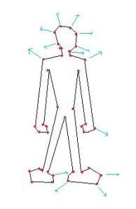
Ocean waves Instead of making a big bone animated mesh to create a realistic looking ocean in your game, you could use a vertex shader to produce waves. To do this, you will need a big flat mesh that will represent your ocean without any waves. You could either do this in 3Ds, or produce it with code. It will need many vertexes, as the shader will move them up and down according to a sine/cos function.
As we can see in this picture, we got a plane defined by a lot of vertices. We can use a Vertex Shader to move all vertexes by its Y-axis with a sine function, say
f(y)=sin(y).
Say vertex Vx ‘s Y-axis is defined by sin(X.pos+time);
This will produce waves on the ocean. Of course, this is really simple and pretty ugly. There is a lot of different Ocean algorithms out there, so if you want to look more closely on this subject, just do a bing the topic.
To make the ocean look better, you could apply a normal map to create small bumps on the surface, in addition to huge waves. You can also mix sine and cos functions to make more realistic waves.
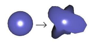
Fake Spherical harmonics
This is what I’m going to implement today. Its pretty much a combination of the slim/fat algorithm and the ocean algorithm. The example will use a sphere object, and apply a pretty advanced sin/cos function to move vertexes along their normal in order to deform it, based on time.
Implementing the shader
The shader is just a Vertex Shader. The pixel shader will only do some basic lighting to make it look more real. You can add normal-mapping here and so on to create really cool looking effects( refer to my previous tutorial on normal mapping ).
In this shader, we will need a time variable, so we can move our vertexes along with a timer to make it look animated, and then we only make a huge mess of sine and cos functions to make it look cool. Feel free to play with these values.
We will use the same shader as in Tutorial #3.
First of all, we must add a timer to the shader so we can create an animation.
float TotalTime;
Then the rest of the effect is happening in the Vertex Shader only, and only the position variable of the vertex is changed.
Here is the Vertex Shader for this effect:
// The VertexShader.
VertexShaderOutput VertexShaderFunction(VertexShaderInput input,float3 Normal : NORMAL)
{
    VertexShaderOutput output;

	// Just some random sin/cos equation to make things look random
    float angle=(TotalTime%360)*2;
    float freqx = 0.4f+sin(TotalTime)*1.0f;
    float freqy = 1.0f+sin(TotalTime*1.3f)*2.0f;
    float freqz = 1.1f+sin(TotalTime*1.1f)*3.0f;
    float amp = 1.0f+sin(TotalTime*1.4)*10.0f;

    float f = sin(Normal.x*freqx + TotalTime) * sin(Normal.y*freqy + TotalTime) * sin(Normal.z*freqz + TotalTime);
    input.Position.z += Normal.z * freqz * amp * f;
    input.Position.x += Normal.x * freqx* amp * f;
    input.Position.y += Normal.y * freqy* amp * f;

    float4 worldPosition = mul(input.Position, World);
    float4 viewPosition = mul(worldPosition, View);
    output.Position = mul(viewPosition, Projection);
	float3 normal = normalize(mul(Normal, World));
	output.Normal = normal;
	output.View = normalize(float4(EyePosition,1.0) - worldPosition);

    return output;
}
It’s all about modifying the position of the vertex, moving them along their normal to shrink/expand the model. Doing this with a sin/cos function, we can create some pretty cool objects. If you for example modify the timer-value with the input from the keyboard or gamepad – you can search for some pretty cool objects, save the parameter and use them as enemies or anything you’d like.
Welcome back to the XNA Shader Programming series. I hope you enjoyed the last 3 tutorials, and have started to get a grip on shaders! Last time we talked about Specular lighting, and how to implement this in our own engines. Today I’m going to take this to the next level, and implement Normal Mapping.
Technique: Normal mapping Normal mapping is a way to make a low-poly object look like a high-poly object, without having to add more polygons to the model. We can make surfaces, like walls; look a lot more detailed and realistic by using the technique described next.
Figure 4.1a – Scene without Normal mapping on Zombie, with Normal Mapping on the background
Figure 4.1b – Scene with Normal mapping on both Zombie and Background
An easy way to describe normal mapping is that it is used to fake the existence of geometry.
To compute normal mapping, we will need two textures: one for the color map, like a stone texture, and a normal map that describes the direction of all the normals on a surface. Instead of calculating the Light by using Vertex-normals, we calculate lighting by using the normals stored in the normal map.
Figure 4.2 – How normal mapping works
Fig.4.2 shows a simple example on normal mapping. We got a stone texture and a normal map, a shader combines these and applies it to a completely spherical surface. But, the Normal map simulates some holes and bumps in the stones surface, making it look less round. As you can see, the edges of the sphere reveals our fake bumps since normal mapping does not physically displace vertexes on a surface.
Tangent space Sounds easy, yes? Well, there is one more thing. In most Normal mapping techniques (like the one I’m describing today), the normals are stored in something that is called texture space coordinate system, or tangent space coordinate system. Since the light vector is handled in object or world space, we need to transform the light vector into the same space as the normals in the normal map.
To describe tangent space, take a look at figure 4.3. Figure 4.3 – Tangent space
We will grab the tangents from the model file, and pass it in to the shader. The shader will then use this to calculate a matrix that will be used to transform the light calculations in tangent space.
To enable this, click the asset and open the tree for the Content processor and set the property that generates tangents to true:
Figure 4.4 – Content Processor
Lets take a closer look on how to implement this later, for now, let’s focus on adding a image file that will represent the color of each surface, textures! Textures can be used to add colors to a wall, a skin on a arm, a dragon-logo on the chest of a warrior and so on. A texture can be any image file, like .jpg, .bmp, .png,
To implement a basic normal map, we will need two textures. One texture for the color map on our model, and one texture that contains the normal map for the model.
Textures To implement textures in HLSL, we need to create something that is called Texture samplers. A texture sampler, as the name describes, sets the sampler state on a texture. This could be info about how the texture should use filtering ( trilinear in our case ), and how the U,V coordinates of the texture map will behave. This can be clamping the texture, mirroring the texture and so on.
To create a sampler for our texture, we first need to define a texture variable the sampler will use:
So, we got a texture and a sampler, next is to put them into use.
Since we are using a pixels shader to map a texture to an object, we can simply create a vector to store the color information. Color got 3 or 4 channels, one for the red color, one for green, one for blue, and in some cases, one for the alpha value of the color. The alpha value represents the transparency of the color.
float4 Color;
New, we need to set the values in the Color variable to equal the color in our texture at texture coordinate UV.
In HLSL, this can easily be done by using a HLSL function called tex2D( s, t ); where s is the sampler, and t is the texture coordinate of the pixel we are currently working on.
float4 color = tex2D(ColorMapSampler, input.TexCoord);
Texture coordinates? Well, let me explain that. A texture coordinate is simply a 2D coordinate ( U,V ) that is stored at each vertex in our 3D model. It is used to map a texture onto the object and is ranging from 0.0 to 1.0.
Figure 4.4 – Texture Coordinates
With texture coordinates, the model can have textures assigned to different places; say an Iris texture on the eyeball part of a human-model, or a mouth somewhere in a human face.
As for the lighting algorithm, we will use Specular lighting in just the same way as earlier, but the normals are fetched from a texture instead of the vertex.
Implementing the shader
The biggest difference in this shader and the specular lighting shader is that we will use tangent space instead of object space, and that the normals used for lighting calculation will be retrieved from a normal map. So the first addition to the shader from the previous tutorial is to define the textures and the texture samplers:
Having the textures ready, we must add the Texture Coordinates to the Vertex Shader Input structure. In here, we also take the Normal, Binormal and the Tangent (generated in the model), ready for use in the Vertex Shader.
Now, in the vertex shader, a lot is still the same as before, but we need to fill the WorldToTangentSpace parameter so we can transform the normals and light-calculations to the correct space.
To implement the WorldToTangentSpace , we multiply each of the components with the World matrix.
Then we create a 3×3 matrix, WorldToTangentSpace, which is used to transform from world space to tangent space.
Basically, what we get from this vertex shader is the transformed Position, and a transformed Light and View vector based on the tangent space matrix. This is because, as mentioned earlier, the normal map is stored in tangent space. So to calculate a proper light based on the normal map, we need to do this to have all vectors in the same space.
So, now that we have our vectors in the right space, we are ready to implement the pixel shader.
The pixel-shader need to get the pixel color from the color map, and the normal from the normal map. Once this is done, we can calculate the ambient, diffuse and specular lighting based on the normal from our normal map.
The code for implementing the pixel shader is also pretty much straight forward – we basically have to change the way the normal is created, and add the color from the texture to our algorithm, have a look at the code:
We get the color from the texture by using the tex2D(s,t) function. It will return the color located at the position t in texture s. We do the same with the normal, but making sure it will range from 0-1 instead of –1 to +1.
The rest is the same as before, except that we add the color value to the ambient, diffuse and specular light.
And that’s basically it! A lot of new concepts was introduced today. Play around with the example to make sure you understand what the variables do.
Binary man is just about to get released. During the game you will need to take out a number of enemies as effective and fast as possible. To kill an enemy, or a block, you will need to shoot it is strategic positions with the right color (floot filler).
One of the first enemies you encounter where you have different kinds of solutions is the Shield Bug.
The Shield Bug is a enemy surrounded by a blue shield. If you do it the right way, you will be able to take it out with 4 shots.
Taking out the Shield Bug
Approach the Shield Bug by either from the top, or the bottom as he shoots straight forward.
Many tend to start by using the purple color on the gun. This will result in being able to kill the Shield Bug with five or more shots as one of the eyes (the right eye) is not connected to the shield in any way.
1) However, if you start with Gray shot first, you’re off from a good start.
2) Now fire of a Purple shot to remove the face.
3) Then Green to remove the eyebrows
4) And lastly, fire off a blue shot to kill it.
And there you have it! Good luck with the rest of the enemies in the game!
Project Binary Man is a 2D-sidescrolling game for Windows Phone. You are a digital-superhero controlled by a scientist who must be able to recover LarsOtek’s new mainframe system.
The game is actually a combination of an action-shooter game and a puzzle game, where each enemy is a puzzle itself. The more effective you can kill an enemy, the more points you will get.
Each level is rated with five stars, where a one star is bad, and five stars is perfect.
As the game is based on a superhero, I decided to make the intro with a comic-style to it.
Just wanted to quickly mention that my article “Modern art using the GPU” article for SDJ was published earlier this year. The article is based on my previous tutorials for XNA 3.1.
As the article is based on XNA 3.1, it’s a bit out of date. My current tutorial series covering Shader programming for XNA 4.0 will cover most of the differences, but all examples, code, shaders and text is rewritten for the new version.
Hi, and welcome to Tutorial 3 of my XNA 4.0 Shader Programming tutorial. Today we are going to implement an other lighting algorithm called Specular Lighting. This algorithm builds on my Ambient and Diffuse lighting tutorials, so if you haven’t been trough them, now is the time.
Technique: Specular light
So far, we got a nice lighting model for making a good looking lighting on objects. But, what if we got a blank, polished or shiny object we want to render? Say a metal surface, plastic, glass, bottle and so on? Diffuse light does not include any of the tiny reflections that make a smooth surface shine.
fig 3.1 – specular light in EVE Online (GREAT game btw.)
To simulate this shininess, we can use a lighting model named Specular highlights. Specular highlights calculate another vector that simulates a reflection of a light source, which hits the camera, or “the eye”.
What’s “the eye” vector, you might think? Well, it’s a pretty easy answer to this. It’s the vector that points from our camera position to the camera target.
We already got this vector in our application code:
viewMatrix = Matrix.CreateLookAt( new Vector3(x, y, z), Vector3.Zero, Vector3.Up );
The position of “The eye” is the first parameter in CreateLookAt:
new Vector3(x, y, z)
So let’s take this vector, and store it in a variable:
Vector4 vecEye = new Vector4(x, y, z,0);
Note: x,y,z represents a point in 3d space.
Let’s look more closely about how to use the shader after we have created it.
The formula for Specular light is
I=Ai*Ac+Di*Dc*N.L+Si*Sc*(R.V)n (3.1)
Where
R=2*(N.L)*N-L
fig 3.2 – Vector diagram for specular light
As we can see, we got the new Eye vector V, and also we got a reflection vector R.
To compute the specular light, we need to take the dot product of R and V and use this in the power of n, where n is controlling how “shiny” the object is.
Implementing the shader
We start with the VertexShader. There is only one modification, and that is to add a View vector to the VertexShaderOutput structure, so we will need to calculate this in the VertexShaderFunction.
struct VertexShaderOutput
{
    float4 Position : POSITION0;
	float3 Normal : TEXCOORD0;
	float3 View : TEXCOORD1;
};
To calculate the View vector V (check figure 3.2), we need the position of the “eye”, in other words – the position of the camera, we will need to add a new global variable to the shader.
float3 EyePosition;
Now, in the vertex shader, we need to set the View-vector in the output structure:
// The output from the vertex shader, used for later processing
struct VertexShaderOutput
{
    float4 Position : POSITION0;
	float3 Normal : TEXCOORD0;
	float3 View : TEXCOORD1;
};

// The VertexShader.
VertexShaderOutput VertexShaderFunction(VertexShaderInput input,float3 Normal : NORMAL)
{
    VertexShaderOutput output;

    float4 worldPosition = mul(input.Position, World);
    float4 viewPosition = mul(worldPosition, View);
    output.Position = mul(viewPosition, Projection);
	float3 normal = normalize(mul(Normal, World));
	output.Normal = normal;
	output.View = normalize(float4(EyePosition,1.0) - worldPosition);

    return output;
}
Now we got what we need to calculate the specular light in the pixel shader!
The pixel shader will return a float4, which represents the finished color, I, of the current pixel, based on the formula for specular lighting described earlier.
The new thing in the Pixel Shader for Specular Lighting is to calculate and use a reflection vector for L by N, and using this vector to compute the specular light.
So, we start with computing the reflection vector of L by N: R = 2 * (N.L) * N – L
As we can see, we have already computed the Dot product N.L when computing the diffuse light.
Note: We could also use the reflect function that is built in to HLSL instead, taking an incident vector and a normal vector as parameters, returning a reflection vector: float3 ref = reflect( L, N );
Now, all there is left is to compute the specular light. We know that this is computed by taking the power of the dot product of the reflection vector and the view vector, by n: (R.V)^n You can think of n as a factor for how shiny the object will be. The more n is, the less shiny it is, so play with n to get the result you like.
As you might have noticed, we are using a new HLSL function pow(a,b). What this does is quite simple, it returns ab.
This formula should no longer be a surprise for anyone, right?
We start by calculating the Ambient and Diffuse light, and add these together. Then we take the specular light color and multiply it with the specular component we just calculated, and add it with the Ambient and Diffuse color we created in the previous techniques.
The whole PixelShaderFunction code can be seen below.
Hi, and welcome to Tutorial 2 of my XNA 4.0 Shader Programming tutorial. Today we are going to work on Tutorial 1 in order to make the lighting equation a bit more interesting, by implementing Diffuse lighting.
Diffuse light isn’t very different from ambient light implementation wise, but it got one very important property, a direction to the light. As we saw, using only ambient light can make a 3D scene look 2D, but adding a diffuse will increase the realism of the scene and add a nice 3D look to it. Figure 1 shows the same zombie we rendered in the first example, but with diffuse white light, and a dark gray ambient light Figure 1 – Diffuse light
As mentioned above, the ambient light got the following equation:
I = Aintensity * Acolor (1.1)
Diffuse light builds on this equation, adding a directional light to the equation:
I = Aintensity x Acolor + Dintensity x Dcolor x N.L (1.2)
From this equation, you can see that we still use the Ambient light, with an addition of two more variables for describing the color and intensity of the Diffuse light, and two vectors N and L for describing the light direction L and the surface normal N.
We can think of diffuse lighting as a value that indicates how much a surface reflects light. The light that is reflected will be stronger and more visible when the angle between the Normal N and the light direction L gets smaller.
If L is parallel with N, the light will be most reflected, and if L is parallel with the surface, the light will be reflected with the minimal amount.
To compute the angle between L and N, we can use the Dot-product, or the scalar product. This rule is used to find the angle between two given vectors and can be defined as the following: N.L = |N| x |L| x cos(a)
where |N| is the length of vector N, |L| is the length of vector L and cos(a) is the angle between the two vectors.
Let’s try to convert this in to HSLS! In order to do this, we start by defining three new global variables:
These will contain the direction of the light ( L ), the color of the diffuse light and the intensity of the light.
The Vertex Shader input is the same as before, containing only the position.
struct VertexShaderInput
{
float4 Position : POSITION0;
};
The VertexShaderOutput will contain one additional member, the Normal. The normal will be calculated in the Vertex Shader function, based on the objects Normal at the given vertex.
struct VertexShaderOutput
{
float4 Position : POSITION0;
float3 Normal : TEXCOORD0;
};
But where do we get this Normal from? We need to pass in the Normal as input to the Vertex Shader! So.. Why didn’t we add it to the VertexShaderInput structure? Because the NORMAL semantic isn’t supported when defining structures in XNA. So how do we get the normals? We pass in the Normal as a parameter to the VertexShaderFunction in addition to the VertexShaderInput parameter. Sounds complicated? Some code might clear it up for you
VertexShaderOutput VertexShaderFunction(VertexShaderInput input,float3 Normal : NORMAL)
Here you can see that we pass in the VertexShaderInput structure, as well as the Normal. When passing in the parameter directly, the NORMAL semantic will work
The Vertex Shader function is very similar to the one in the ambient light tutorial, but we also transform the Normal into worldspace, as this is the space we would like to calculate the normal in, just like the position:
So what’s really happening here? We take the input Normal and multiply it with the World matrix, and then we normalize it and store it in a variable normal. Next, we must remember to set the Normal variable in output, to make sure it’s passed to the Pixel Shader by setting output.Normal = normal.
And that’s really it for the Vertex Shader. But it’s still in the Pixel Shader most of the “magic” happens.
In order to pass the Normal to the pixel shader, we added a float3 Normal : TEXCOORD0 variable to the VertexShaderOutput structure. We needed to store the Normal in a register on the GPU, but since NORMAL doesn’t exist, we just used another one that is not in use yet; the TEXCOORD0. In other words, TEXCOORDn (n = any number up to the supported amount of registers on your GPU, anything between 0 and 7 is usually safe to use) can be used for any values, and as we don’t yet use any texture coordinates, we can easily just use these registers as a storage for our Normal-vector.
Moving on. The pixel shaders job is to calculate the final light equation. It will need to implement 1.2:
I = Aintensity x Acolor + Dintensity x Dcolor x N.L
We already got Aintensity and Acolor. Also, the Dintensity and Dcolor are just variables passed in to the shader, just as the ambient light.
But what about the last part? N.L? This means that we take the dot-product between N and L (remember, the angel of the incoming light, “compared” with the Normal).
Let’s try! First, we store our Normal vector, and convert it to a float4, as this is the variable-type we use in the other calculations. When we use the build in HLSL function dot(x,y) to calculate the dot-product between L and N. Also, we negate L as the value L is containing the direction the light comes FROM, and not where the light points TO.
Now, all that is left is to put this into eq. 1.2 like the code shows below:
Now if you apply this shader to a scene, the output will be something like this:
There is nothing new when it comes to how this shader is used in XNA. Take a look at the source so see how it all fits together and play with the values.
The complete shader listing can be seen below:
// XNA 4.0 Shader Programming #2 - Diffuse light
// Matrix
float4x4 World;
float4x4 View;
float4x4 Projection;
// Light related
float4 AmbientColor;
float AmbientIntensity;
float3 DiffuseDirection;
float4 DiffuseColor;
float DiffuseIntensity;
// The input for the VertexShader
struct VertexShaderInput
{
    float4 Position : POSITION0;
};
// The output from the vertex shader, used for later processing
struct VertexShaderOutput
{
    float4 Position : POSITION0;
	float3 Normal : TEXCOORD0;
};
// The VertexShader.
VertexShaderOutput VertexShaderFunction(VertexShaderInput input,float3 Normal : NORMAL)
{
    VertexShaderOutput output;

    float4 worldPosition = mul(input.Position, World);
    float4 viewPosition = mul(worldPosition, View);
    output.Position = mul(viewPosition, Projection);
	float3 normal = normalize(mul(Normal, World));
	output.Normal = normal;

    return output;
}
// The Pixel Shader
float4 PixelShaderFunction(VertexShaderOutput input) : COLOR0
{
	float4 norm = float4(input.Normal, 1.0);
	float4 diffuse = saturate(dot(-DiffuseDirection,norm));

    return AmbientColor*AmbientIntensity+DiffuseIntensity*DiffuseColor*diffuse;
}
// Our Techinique
technique Technique1
{
pass Pass1
{
VertexShader = compile vs_2_0 VertexShaderFunction();
PixelShader = compile ps_2_0 PixelShaderFunction();
}
}
Hi and welcome to tutorial #4 in my Kinect Fundamentals tutorial. In this tutorial, I will show you how you can implement Skeletal Tracking using the Kinect SDK for Windows API, and how you can move a cursor by using your hand.
Note: This tutorial has been updated from the Kinect for Windows SDK beta to the Kinect for SDK 1.0. Most of the code since the previos tutorial was changed.
It’s very simple, and it is quite similar to the approaches we have used in the previous tutorials.
Let’s get started!
The example will render the captured image from the device, as well as render a cursor/ball in the hands of the player. The approach is very similar to the previous tutorials. We must enable the SkeletonStream on out KinectSensor instance in the InitializeKinect() function.
After the Kinect knows that is should start tracking the skeleton, you must tell it how it should be done. You got a lot of different parameters to do this, and the key is to play around with these until you are satisfied.
Play around with the parameters to see what they do. Basically, it’s all about if you want smooth transforming or not, and how the Kinect should anticipate your movement and handle it.
Tracking Joints
We start listening to the SkeletonFrameReady event so we can handle a skeleton each time the Kinect captures a new.
Let’s look at the code, an explanation is given below.
void kinectSensor_SkeletonFrameReady(object sender, SkeletonFrameReadyEventArgs e)
{
    using (SkeletonFrame skeletonFrame = e.OpenSkeletonFrame())
    {
        if (skeletonFrame != null)
        {
            int skeletonSlot = 0;
            Skeleton[] skeletonData = new Skeleton[skeletonFrame.SkeletonArrayLength];

            skeletonFrame.CopySkeletonDataTo(skeletonData);
            Skeleton playerSkeleton = (from s in skeletonData where s.TrackingState == SkeletonTrackingState.Tracked select s).FirstOrDefault();
            if (playerSkeleton != null)
            {
                Joint rightHand = playerSkeleton.Joints[JointType.HandRight];
                handPosition = new Vector2((((0.5f * rightHand.Position.X) + 0.5f) * (640)), (((-0.5f * rightHand.Position.Y) + 0.5f) * (480)));
            }
        }
    }
}
First you get all the skeletons in the returned collection. Then we find all the skeletons that belong to the player currently being tracked (this is automatic), and find the joint of the Right Hand. This joint includes a position that you simply can use to render your object at.
The formula I created when rendering the object is not very accurate but it get’s the job done. This is because I simply just use the X and Y of a 3D point, leaving the Z. This means that we bypass the depth of the scene so at point’s it will be wrong as we didn’t implement depth.
The Kinect returns a position between –1 (left) and 1 (right). I use this to convert the number to the range is 0 to 1 since the resolution of the scene is from 0 to 640 and 0 to 480. I then multiply the position with the resolution so the cursor can move around on the entire scene.
So, you want to learn the magic that puts the gold into modern games?
Note: This series is an update to the previous XNA Shader Programming series I have written for XNA 3.0. If you know both XNA 3.0 and XNA 4.0, it should be no problem for you to understand the shaders from the other series if you want to move on faster than I can update the old ones.
My name is Petri Wilhelmsen and is a member of Dark Codex Studios. We usually participate in various competitions regarding graphics/game development, at The Gathering, Assembly, Solskogen, Dream-Build-Play, NGA and so on.
The XNA Shader Programming series will cover many different aspects of XNA, and how to write HLSL shaders using XNA and your GPU. I will start with some basic theory, and then move over to a more practical approach to shader programming.
The theory part will not be very detailed, but should be enough for you to get started with Shaders and be able to experiment for yourself. It will cover the basics around HLSL, how the HLSL language works and some keywords that is worth knowing about.
Today I will cover XNA and HLSL, as well as a simple ambient lighting algorithm.
Prerequisites Some programming in XNA (this tutorial is about shader programming and not XNA in it self), as I wont go much into details about loading textures, 3d models, matrices and some math.
2001: A shader odyssey – A brief history of shaders Before DirectX8, GPU’s had a fixed way to transform pixels and vertices, called “The fixed pipeline”. This made it impossible to developers to change how pixels and vertices was transformed and processed after passing them to the GPU, and made games looked quite similar graphics wise.
In 2001, DirectX8 introduced the vertex and pixel shaders, as a utility that developers could use to decide how the vertices and pixels should be processed when going through the pipeline, giving them a lot of flexibility. An assembly language was used to program the shaders, something that made it pretty hard to be a shader developers, and shader model 1.0 was the only supported version. But this changed once DirectX9 was released, giving developers the opportunity to develop shaders in a high level language, called High Level Shading Language( HLSL ), replacing the assembly shading language with something that looked more like the C-language. This made shaders much easier to write, read and understand.
DirectX10.0 introduced a new shader, the Geometry Shader, and was a part of Shader Model 4.0. But this required a new state-of-the-art graphics card, and Windows Vista.
The latest addition to the DirectX series is the DirectX 11 including a tesselator, DirectCompute for paralell programming and much more.
XNA supports Shader Model 1.0 to 3.0, but works on XP, Vista and XBox360!
Taking the red pill So, the question is.. What is a shader? Well, a shader is simply a set of instructions that will be run on you graphics processing unit (GPU), performing specific tasks of you need. This makes it possible to developer small/tiny applications that make you in control of three stages in the graphics pipeline: The vertex shader stage, the geometry shader stage, and the pixel shader stage.
Fig 1 –High level Programmable pipeline
As you can see in fig 1, you are able to program all the green squares, and the rest is fixed, meaning that you cannot control them. The geometry shader is not supported by Xbox360 and XNA, so it will not be covered in this article. Rather, let’s take a quick tour through the vertex and pixel shaders (don’t get frustrated if you don’t understand the code yet, it will be covered in a later section).
Vertex shader Vertex shaders are used to manipulate vertex-data, per vertex. This can for example be a shader that makes a model “fatter” during rendering by moving vertexes along their normals to a new position for every vertex in the model (deform shaders). Vertex shaders get input from a vertex structure defined in the application code, and load this from the vertex buffer, passed into the shader. This describes what properties each vertex will have during shading: Position, Color, Normal, Tangent and so on.
The vertex shader sends its output for later use to the pixel shader. To define what data the vertex shader will pass to the next stage can be done by defining a structure in the shader, containing the data you want to store, and make the vertex shader return this instance, or by defining parameters in the shader, using the out keyword. Output can be Position, Fog, Color, Texture coordinates, Tangets, Light position and so on.
An example of a simple Vertex Shader that transforms an object to a position on the screen can be seen below.
Pixel shader The Pixel shader manipulates all pixels (per pixel) on a given model/object/collection of vertices. This can be a metal box, where we want to customize the lighting algorithm on, colors and so on. The pixel shader gets data from the vertex shader’s output values, like position, normals and texture coordinates, and interpolates these values to the different pixels. A very simple and small pixel shader can look like the snippet below.
The code colors everything that flows through the shader RED.
The pixel shader can have two output values, Color and Depth.
All of the stages displayed in Fig 1 are working together in order to synthesize images and display them on the monitor.
So, are you ready to take control of the GPU using shaders? In that case, sit back, you are about to join a long ride and be reborn in the world of shaders.
HLSL High Level Shading Language(HLSL) is used to develop shaders using a language similar to C. Just as in C, HLSL gives you tools like declaring variables, functions, data types, testing( if/else/for/do/while and so on) and much more, in order to create a logic for processing vertices and pixels. Below is a table of some keywords that exists in HLSL. This is not all of them, but some of the most important ones.
Examples of datatypes in HSLS
bool
true or false
int
32-bit integer
half
16bit integer
float
32bit float
double
64bit double
Examples of vectors in HSLS
float3 vectorTest
float x 3
float vectorTest[3]
float x 3
vector vectorTest
float x 3
float2 vectorTest
float x 2
bool3 vectorTest
bool x 3
Matrices in HSLS
float3x3
a 3×3 matrix, type float
float2x2
a 2×2 matrix, type float
HSLS offers a huge set of functions that can be used to solve complex equations. As we go through this article, we will cover many, but for now, here is a list with just a handful of them. It’s important to learn all of them in order to create high-performance shaders without re-implementing the wheel.
Effect files Effect files (.fx) makes shader developing in HSLS easier. You can think of them as containers where you can store shader functionality, including vertex-, geometry- and pixel shaders. This includes global variables, functions, structures, vertex shader functions, pixel shader functions, different techniques/passes, textures and so on.
We have already seen how to declare variables and structures in a shader, but what is this technique/passes thing? It’s pretty simple. One Shader can have one or more techniques. One Technique is a piece of functionality that represents one functionality of a given .fx file. Each technique can have a unique name, and from the game/application, we can select what technique in the shader we want to used when rendering a given geometry, by setting the CurrentTechnique property of the Effect class like this:
One .fx file represents one effect. On the line above, we tell the effect to use the technique “AmbientLight”. One technique can have one or more passes, and we must remember to process all passes in order to archive the result we want.
This is an example of a shader containing one technique named “AmbientLight” and one pass named “P0”:
This is an example of a shader containing one technique and two passes: technique Shader { pass P0 { VertexShader = compile vs_1_1 VS(); PixelShader = compile ps_1_1 PS(); } pass P1 { VertexShader = compile vs_1_1 VS_Other(); PixelShader = compile ps_1_1 PS_Other(); } }
This is an example of a shader containing two techniques and one pass: technique Shader_11 { pass P0 { VertexShader = compile vs_1_1 VS(); PixelShader = compile ps_1_1 PS(); } }
We can see that a technique got two functions, one for the pixel shader and one for the vertex shader: VertexShader = compile vs_1_1 VS2(); PixelShader = compile ps_1_1 PS2();
This tells us that the technique will use VS2() function as the vertex shader, PS2() function as the pixel shader, and the shader requires shader model 1.1 or higher. This makes it possible to have a different and more complex shader for GPUs supporting higher shader model versions, and simpler shaders for older hardware that only support the earlier shader models.
XNA and shaders It’s really easy to implement shaders in XNA. In fact, only a few lines of code are needed to load and use a shader. Here is a list of steps that can be followed when making a shader, each of them covered in detail below: 1. Make the shader 2. Put the shade file (.fx) in “Contents” 3. Make an instance of the Effect class 4. Initiate the instance of the Effect class. 5. Select what technique you want to use 6. Pass different parameters to the shader 7. Draw the scene/object
The steps in a bit more detail:
1.When making a shader, several programs like notepad, the visual studio editor and so on can be used. There are also some shader IDEs available, and personally I like to use nVidias FX Composer: http://developer.nvidia.com/object/fx_composer_home.html
2. When the shader is created, drag it into the ”Content” folder, so it gets an asset name. The asset name will be the same as the filename of the fx file, but you can edit this asset name so it better suits your needs.
3. XNA Framework includes an Effect class that is used to load and compile the shaders. To make an instance of this class, write the following line of code:
Effect effect; Effect is a part of the “Microsoft.Xna.Framework.Graphics” library, so remember to add this line of code to the using statement block: using Microsoft.Xna.Framework.Graphics;
4. To initiate the shader, we can use the Content property to either load if from the project or from a file:
effect = Content.Load<Effect>(“Shader”); In the line above, “Shader” is the asset name of the shader you added to the Contents folder.
5. Select what technique you want to use: effect.CurrentTechnique = effect.Techniques[“AmbientLight”];
6. Pass the parameters you want to set in the shader.
First you need to create a EffectParamter object: EffectParameter projectionParameter;
Then in the LoadContent() function you bind the parameter object with a variable in the shader: projectionParameter = effect.Parameters[“Projection”];
Now, you can set the parameter by using the SetValue function like this: projectionParameter.SetValue(projection);
where projection is a matrix (here: representing the projection matrix).
7. All that is left is to go through all the different passes in the shader and render your object. This is done by using a loop:
for (int i = 0; i < effect.CurrentTechnique.Passes.Count; i++)
{
    //EffectPass.Apply will update the device to
    //begin using the state information defined in the current pass
    effect.CurrentTechnique.Passes[i].Apply();

    //sampleMesh contains all of the information required to draw
    //the current mesh
    graphics.GraphicsDevice.DrawIndexedPrimitives(
        PrimitiveType.TriangleList, 0, 0,
        meshPart.NumVertices, meshPart.StartIndex, meshPart.PrimitiveCount);
}
Technique: Ambient light So, you now got the answer to what a shader is! Let’s take that in to use and create your first real shader! The first shader you will write is a really simple one that just transforms the vertexes and calculates the ambient light on the model. But wait… What is the “Ambient light” thing we are talking about?
Well, ambient light is the basic light in a scene that’s “just there”. If you go into a complete dark room, the ambient light is typically zero, but when walking outside there is almost always some light that makes it possible to see. This light got no direction and is there to make sure objects that are facing a light source, will have a basic color.
A scene with only a yellow ambient light can be seen in figure 2. The scene consists of a black background color and an un-textured zombie model. We will make this zombie scene look a lot better as we are going through this series.
Fig 2. Scene lit with ambient light.
Before we can implement the ambient light technique, we need to understand it. The formula for Ambient light can be seen in 1.1 below. I = Aintensity x Acolor ( 1.1)
I is the final light color on a given pixel, Aintensity is the intensity of the light (usually between 0.0 (0%) and 1.0 (100%)), and Acolor is the color of the ambient light. This color can be a hardcoded value, a parameter or a texture.
Ok, let’s start implementing the shader. First of all, we need a matrix that represents the world matrix, the view matrix and the projection matrix:
You might also notice that we added two variables in the end, the AmbientColor and AmbientIntensity. I don’t think I need to explain those now?
Next, we create a structure that will contain the shader inputs, and outputs. These are used in the Vertex Shader itself.
The structures contains a variable of the type float4 with the name Position. The : POSITION in the end tells the GPU what register to put this value in. So, what is a register? Well, a register is simply just a container in the GPU that contains data. The GPU got different registers to put position data, normal, texture coordinates and so on, and when defining a variable that the shader will pass to the pixel shader, we must also decide where in the GPU this value is stored.
When declaring the Vertex Shader function “VertexShaderFunction” (works like the main() function for Vertex Shaders), we specify that the function should return a VertexShaderOutput object (you can name the structure yourself, it could be VSOut and so on), and it takes in the VertexShaderInput structure. All that the shader needs to to is to create an instance of the VertexShaderOutput structure, set its members and return it.
This is a basic “pass-through” shader. It will take the position of the vertex in the model and transform it to the correct space.
Next we create the Pixel Shader function, where we will compute the Ambient Light. This takes the output from the Vertex Shader as input. It’s a simple function that takes the pixel it is working on, and color it to the AmbientColor*AmbientIntensity. Simply: A color, the color of the given pixel. Remember, pixel shaders works with one and one pixel at a time.
Now, i recommend you to look at the source code and play around with the values in order to understand how to setup and implement a shader using XNA. Especially, take a look at how the shader is loaded and what parts is needed. I have tried to minimize everything so the code mostly only consists of Shader related code. The camera spins around the model by using a Cos/Sin function on the view matrix.
Thank you for considering giving a small donation! Any donations is really apprechiated, and will go to creating more content and tutorials on this blog.