XNA Shader Programming
Tutorial 14 – Transmittance

Welcome to the 14th tutorial in the XNA Shader Programming tutorial. Last time, we looked at using alpha maps and the alpha channel to make objects look transparent. Today we are going to dive a bit deeper in transparency, by implementing transmittance.
Transmittance
Things like glass, water, crystal, gass, air++ are things that absorb light as light-rays pass through them. In tutorial 13, we used alpha maps to make things look transparent and could create a transparent glass ball by just creating an alphamap with the color RGB(0.5,0.5,0.5) and we got ourself a transparent glassball. This approach works well in many cases, but it makes the transparency quite flat.
Objects in the real world, say a glass sphere, absorb/scatters light as the light-rays pass trough them. The longer the rays are inside the glass-ball, the more light will be scattered and absorbed before comming out. This is called Transmittance( wikipedia ).
To calculate the transmittance( T ), we can use Beer-Lamberts law ( wikipedia ) on the light-rays that pass trough the transmitter. Lets take a look at Beer-Lamberts law, and understand what we need calculate!
Beer-Lamberts law:
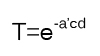 [1]
[1]
where T is the transmittance, a’ is the absorbtion factor, c is the consistensy of the absorbing object and d is the thickness of the object.
So, in order to use this, we need to find a’, c and d.
Let’s start with c. c controls how much light is absorbed when traveling through the transmitter. This value can just be set to any user spesific number above 0.0.
Next is a’. We see a’ in [1], and can use that to find a’:
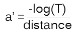 [2]There T is the darkest transmitting color, and that is reached at distance.
Finally, we got the c-variable. This variable is set to the thickness of the object, at a given point, and probably is the hardest part to get right.
In this tutorial, we are calculating c quite correct for any non-complex objects( those that does not contain any holes or "arms" sticking out, like a sphere, simple glass figures and so on). The object used in this shader is a complex one, because we are going to get it right in a later tutorial, but let’s start simple!
Now that we got all variables needed to calculate T at a given point, we can use this to see how much light is absorbed. This is done by multiplying the color of the light-ray( pixel behind the transmitter ) with T!
So, how do we calculate the distance each light-ray is traveling through the transmitter? By using the depth buffer( wikipedia )!
[2]There T is the darkest transmitting color, and that is reached at distance.
Finally, we got the c-variable. This variable is set to the thickness of the object, at a given point, and probably is the hardest part to get right.
In this tutorial, we are calculating c quite correct for any non-complex objects( those that does not contain any holes or "arms" sticking out, like a sphere, simple glass figures and so on). The object used in this shader is a complex one, because we are going to get it right in a later tutorial, but let’s start simple!
Now that we got all variables needed to calculate T at a given point, we can use this to see how much light is absorbed. This is done by multiplying the color of the light-ray( pixel behind the transmitter ) with T!
So, how do we calculate the distance each light-ray is traveling through the transmitter? By using the depth buffer( wikipedia )!
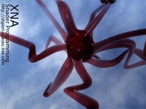
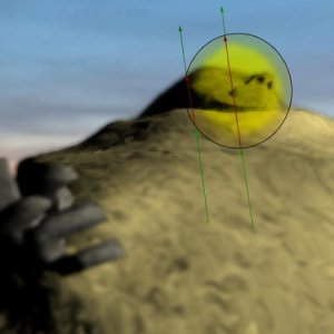
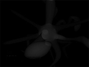
The Depth buffer( Z-Buffer ) can be thought of as a grayscale image containing the scene is black and white, where the grayscale value indicates how far away an object is from the camera. So, if you take a look at the image on top of the article, we see a complex glass object. The scenes depth buffer looks something like this:
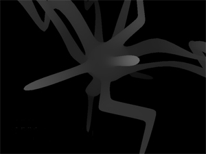 The depth buffer needs to have correct values in the Near and Far clipping plane of the projection matrix. Preferably having Near at the closest( to the view/camera) vertex of the transmitter, and Far at the most distance vertex of the transmitter.
So, knowing this, we can find the thickness of the transmitter from any angle of it, by using two depth buffer textures. By using culling, we can render the front faces of the transmitting object in one depth texture, and the backfaces of the transmitter into another depth texture. Taking the difference in these two gives us the distance on every pixel:
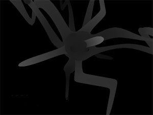
Backfaces in one depth texture.
Frontfaces in another depth texture
Giving us a texture that can look like this. The grayscale value indicates how far a light-ray have to travel to get through the transmitter. White is far, and black is short/nothing.
We are going to look at how to get the depth buffer and render it to a texture in the "Using the shader" section of the tutorial, but first, let’s see how to implement the shaders.
Implementing the Shader
In this tutorial, we got three techniques. One is just rendering the object with specular light( as seen in tutorial 3 ), the other one is rendering the scene to a depth texture, and the last shader is the post process shader that will add transmittance to the objects.
We don’t want ALL objects rendered in a scene to defined as a transmitter. As this is a post process shader, we can first render the scene without the transmitters into one texture( a background texture ), and then render the transmitters alone in a 2nd pass, and then combining these in the post process shader.
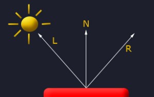
Given this information, let’s start with the specular light shader:
float4x4 matWorldViewProj;
float4x4 matInverseWorld;
float4 vLightDirection;
float4 vecLightDir;
float4 vecEye;
float4 vDiffuseColor;
float4 vSpecularColor;
float4 vAmbient;
texture ColorMap;
sampler ColorMapSampler = sampler_state
{
Texture = <ColorMap>;
MinFilter = Linear;
MagFilter = Linear;
MipFilter = Linear;
AddressU = Clamp;
AddressV = Clamp;
};
struct OUT
{
float4 Pos : POSITION;
float2 Tex : TEXCOORD0;
float3 L : TEXCOORD1;
float3 N : TEXCOORD2;
float3 V : TEXCOORD3;
};
OUT VertexShader( float4 Pos: POSITION, float2 Tex : TEXCOORD, float3 N: NORMAL )
{
OUT Out = (OUT) 0;
Out.Pos = mul(Pos, matWorldViewProj);
Out.Tex = Tex;
Out.L = normalize(vLightDirection);
Out.N = normalize(mul(matInverseWorld, N));
Out.V = vecEye – Pos;
return Out;
}
float4 PixelShader(float2 Tex: TEXCOORD0,float3 L: TEXCOORD1, float3 N: TEXCOORD2, float3 V: TEXCOORD3) : COLOR
{
float3 ViewDir = normalize(V);
// Calculate normal diffuse light.
float4 Color = tex2D(ColorMapSampler, Tex);
float Diff = saturate(dot(L, N));
float3 Reflect = normalize(2 * Diff * N – L);
float Specular = pow(saturate(dot(Reflect, ViewDir)), 128); // R.V^n
// I = A + Dcolor * Dintensity * N.L + Scolor * Sintensity * (R.V)n
return Color*vAmbient + Color*vDiffuseColor * Diff + vSpecularColor * Specular;
}
technique EnvironmentShader
{
pass P0
{
VertexShader = compile vs_2_0 VertexShader();
PixelShader = compile ps_2_0 PixelShader();
}
}
This shader is just a specular light shader, quite similar to the one we made in
Tutorial 3 ( using the exact same lighting-algoritm ) so if this is new, you can see the explanation of this there.
Let’s continue with our Depth Texture shader. This shader will only render the scene in grayscale, where the depth of each vertex/pixel is represented with a value between 0.0 and 1.0, where 1.0 is near the camera and 0.0 is at the far-plane of our shader( Pos.w ).
So, to get the depth vertex, we simply take the Z-value of the given vertex, and devide it with it’s W-value to make it range between the Near and Far clipping plane of our projection matrix.
The vertex-shader will calculate two values: position and distance
struct OUT_DEPTH
{
float4 Position : POSITION;
float Distance : TEXCOORD0;
};
Knowing this, we are ready to implement the Depth texture vertex shader:
OUT_DEPTH RenderDepthMapVS(float4 vPos: POSITION)
{
OUT_DEPTH Out;
// Translate the vertex using matWorldViewProj.
Out.Position = mul(vPos, matWorldViewProj);
// Get the distance of the vertex between near and far clipping plane in matWorldViewProj.
Out.Distance.x = 1-(Out.Position.z/Out.Position.w);
return Out;
}
First, we translate our vertex correctly to our world*view*projection matrix. Then we set the distance value to the correct depth-value. This is done by using the Position.z / Position.w, giving us the depth between the projections Near and Far plane.
Now, it’s the pixel shaders turn to show her magic! Oh, well, there ain’t much magic in there. All we got left is to convert the Distance-value in OUT_DEPTH to a texture, so we can use this later:
float4 RenderDepthMapPS( OUT_DEPTH In ) : COLOR
{
return float4(In.Distance.x,0,0,1);
}
And the technique:
technique DepthMapShader
{
pass P0
{
ZEnable = TRUE;
ZWriteEnable = TRUE;
AlphaBlendEnable = FALSE;
VertexShader = compile vs_2_0 RenderDepthMapVS();
PixelShader = compile ps_2_0 RenderDepthMapPS();
}
}
Nothing new here, we just have to make sure we got the Z buffer enabled, and have it writeable.
And now, the shader this tutorial is really about, the transmittance post process shader!
First of all, we need the Background scene texture, the transmitting objects scene( the texture contianing all of the objects that will be transmitters ) and the two depth buffer textures!
texture D1M;
sampler D1MSampler = sampler_state
{
Texture = <D1M>;
MinFilter = Linear;
MagFilter = Linear;
MipFilter = Linear;
AddressU = Clamp;
AddressV = Clamp;
};
texture D2M;
sampler D2MSampler = sampler_state
{
Texture = <D2M>;
MinFilter = Linear;
MagFilter = Linear;
MipFilter = Linear;
AddressU = Clamp;
AddressV = Clamp;
};
texture BGScene;
sampler BGSceneSampler = sampler_state
{
Texture = <BGScene>;
MinFilter = Linear;
MagFilter = Linear;
MipFilter = Linear;
AddressU = Clamp;
AddressV = Clamp;
};
texture Scene;
sampler SceneSampler = sampler_state
{
Texture = <Scene>;
MinFilter = Linear;
MagFilter = Linear;
MipFilter = Linear;
AddressU = Clamp;
AddressV = Clamp;
};
DM1 is the first depth map texture, containing our transmitters back-faces. DM2 is the 2nd depth map texture, containing our transmitters front-faces, BGScene is containing our background scene, and Scene contains our transmitters scene/color.
Then, we need to add two variables. One will contain the distance factor used to calculate the absorbtion factor, and the other one will contain the consistency of the transmitter:
float Du = 1.0f;
float C = 12.0f;
As this is a post process shader, we won’t need a vertex shader. Let’s start on the pixel shader:
float4 PixelShader(float2 Tex: TEXCOORD0) : COLOR
{
float4 Color=tex2D(SceneSampler, Tex);
float4 BGColor=tex2D(BGSceneSampler, Tex);
float depth1=tex2D(D1MSampler, Tex).r;
float depth2=tex2D(D2MSampler, Tex).r;
Nothing new here, we are getting the pixels from different textures. depth1 and depth2 contains the r-channel the depth texture shader returned.
Let’s take a look at the formula for transmittance again and see what variables we need to get:
So far, we only got the c-variable and the distance-variable. Let’s go and get the rest, shall we? 😉
The d-variable, that will contain the thickness of the transmitter object, can easly be calculated using depth1 and depth2:
float distance = ((depth2-depth1));
Here we take the difference in depth2 and depth1, resulting in the objects thickness!
The T-variable used to find the absorbtion fact at the max in [2], contains the darkest color. This could be a color hardcoded in, or sent to the shader as a parameter. In this tutorial, we are using the value found in Color( the transmitter objects, rendered to a texture ). This gives us the last variable we need to calculate the absorbtion factor a’:
float3 a;
a.r = (-log(Color.r))/Du;
a.g = (-log(Color.g))/Du;
a.b = (-log(Color.b))/Du;
This gives us the last variable needed to calculate out transmittance!
float4 T;
T.r = exp((-a.r)*C*distance)+0.000001;
T.g = exp((-a.g)*C*distance)+0.000001;
T.b = exp((-a.b)*C*distance)+0.000001;
T.w = 1;
We calculate the transmittance value on each color-channel, using [1]. To avoid the T value of 0( making the object completly black ), we add 0.000001 to each channel.
Once this is done, we can take the pixels that exists behind the transmitter( the light-rays traveling through the transmitter ) and multiply it with T. As this is what we want with this shader, we return it from the pixel shader:
return T*BGColor;
And finally, the technique:
technique PostProcess
{
pass P0
{
// A post process shader only needs a pixel shader.
PixelShader = compile ps_2_0 PixelShader();
}
}
Phew, what a shader. It’s not a very complex shader, but it’s probably more advanced than any of the other shaders in my shader tutorial this far. So, in other words, if you don’t understand it all, play around with parameters and the math, to see how each variable works. 🙂
The whole shader look like this:
// Global variables
float Du = 1.0f;
float C = 12.0f;
// This will use the texture bound to the object( like from the sprite batch ).
sampler ColorMapSampler : register(s0);
texture D1M;
sampler D1MSampler = sampler_state
{
Texture = <D1M>;
MinFilter = Linear;
MagFilter = Linear;
MipFilter = Linear;
AddressU = Clamp;
AddressV = Clamp;
};
texture D2M;
sampler D2MSampler = sampler_state
{
Texture = <D2M>;
MinFilter = Linear;
MagFilter = Linear;
MipFilter = Linear;
AddressU = Clamp;
AddressV = Clamp;
};
texture BGScene;
sampler BGSceneSampler = sampler_state
{
Texture = <BGScene>;
MinFilter = Linear;
MagFilter = Linear;
MipFilter = Linear;
AddressU = Clamp;
AddressV = Clamp;
};
texture Scene;
sampler SceneSampler = sampler_state
{
Texture = <Scene>;
MinFilter = Linear;
MagFilter = Linear;
MipFilter = Linear;
AddressU = Clamp;
AddressV = Clamp;
};
// Transmittance
float4 PixelShader(float2 Tex: TEXCOORD0) : COLOR
{
float4 Color=tex2D(SceneSampler, Tex);
float4 BGColor=tex2D(BGSceneSampler, Tex);
float depth1=tex2D(D1MSampler, Tex).r;
float depth2=tex2D(D2MSampler, Tex).r;
float distance = ((depth2-depth1));
float3 a;
a.r = (-log(Color.r))/Du;
a.g = (-log(Color.g))/Du;
a.b = (-log(Color.b))/Du;
float4 T;
T.r = exp((-a.r)*C*distance)+0.000001;
T.g = exp((-a.g)*C*distance)+0.000001;
T.b = exp((-a.b)*C*distance)+0.000001;
T.w = 1;
return T*BGColor;
}
technique PostProcess
{
pass P0
{
// A post process shader only needs a pixel shader.
PixelShader = compile ps_2_0 PixelShader();
}
}
Using the shader
Finally, let us see how we can use the shader from code, and how to set up the depth buffers.
Lets start by defining our render targets and render textures:
RenderTarget2D depthRT;
DepthStencilBuffer depthSB;
RenderTarget2D depthRT2;
DepthStencilBuffer depthSB2;
Texture2D depth1Texture;
Texture2D depth2Texture;
We got two render targets, two stencil buffers and two textures that will contain our depth texture. We could use just one depth stencil buffer it we wanted but for simplicity, i’ll do the same thing on both.
Also, in this shader, we are going to set the technique we want to enable in a shader using variables:
EffectTechnique environmentShader;
EffectTechnique depthMapShader;
Also, we need to set the distance factore used to calculate the absorbtion, and the consitency of our trasmitter:
float Du = 1.0f;
float C = 12.0f;
Now we are ready to start making the scene and using the shader. In LoadContent, we need to initate and create our render targets:
// Create our render targets
PresentationParameters pp = graphics.GraphicsDevice.PresentationParameters;
renderTarget = new RenderTarget2D(graphics.GraphicsDevice, pp.BackBufferWidth, pp.BackBufferHeight, 1, graphics.GraphicsDevice.DisplayMode.Format);
depthRT = new RenderTarget2D(graphics.GraphicsDevice, pp.BackBufferWidth, pp.BackBufferHeight, 1, SurfaceFormat.Single); // 32-bit float format using 32 bits for the red channel.
depthRT2 = new RenderTarget2D(graphics.GraphicsDevice, pp.BackBufferWidth, pp.BackBufferHeight, 1, SurfaceFormat.Single); // 32-bit float format using 32 bits for
the red channel.
We also need to get our DepthStencilBuffers:
depthSB = CreateDepthStencil(depthRT, DepthFormat.Depth24Stencil8);
depthSB2 = CreateDepthStencil(depthRT2, DepthFormat.Depth24Stencil8);
This creates two DepthStencilBuffers using our depth render targets and setting the depth format to Depth24Stencil8, witch sets our DepthBuffer-channel to 24bit and our stencil buffer channel to 8-bit. Here is a list of the different values we can set our DepthFormat to:
|
|
|
| Depth15Stencil1 |
A 16-bit depth-buffer bit depth in which 15 bits are reserved for the depth channel and 1 bit is reserved for the stencil channel. |
|
| Depth16 |
A 16-bit depth-buffer bit depth. |
|
| Depth24 |
A 32-bit depth-buffer bit depth that uses 24 bits for the depth channel. |
|
| Depth24Stencil4 |
A 32-bit depth-buffer bit depth that uses 24 bits for the depth channel and 4 bits for the stencil channel. |
|
| Depth24Stencil8 |
A non-lockable format that contains 24 bits of depth (in a 24-bit floating-point format − 20E4) and 8 bits of stencil. |
|
| Depth24Stencil8Single |
A 32-bit depth-buffer bit depth that uses 24 bits for the depth channel and 8 bits for the stencil channel. |
|
| Depth32 |
a 32-bit depth-buffer bit depth. |
|
| Unknown |
Format is unknown. |
We use two custom functions to create our depth buffers. CreateDepthStencil(RenderTarget2D target) creates the DepthStencilBuffer using the rendertarget passed in to it:
private DepthStencilBuffer CreateDepthStencil(RenderTarget2D target)
{
return new DepthStencilBuffer(target.GraphicsDevice, target.Width,
target.Height, target.GraphicsDevice.DepthStencilBuffer.Format,
target.MultiSampleType, target.MultiSampleQuality);
}
And the 2nd one checks the computers support and uses CreateDepthStencil(RenderTarget2D target) to create the DepthStencilBuffer:
private DepthStencilBuffer CreateDepthStencil(RenderTarget2D target, DepthFormat depth)
{
if (GraphicsAdapter.DefaultAdapter.CheckDepthStencilMatch(DeviceType.Hardware,
GraphicsAdapter.DefaultAdapter.CurrentDisplayMode.Format, target.Format,
depth))
{
return new DepthStencilBuffer(target.GraphicsDevice, target.Width,
target.Height, depth, target.MultiSampleType, target.MultiSampleQuality);
}
else
return CreateDepthStencil(target);
}
Next we need to get our techniques from our shaders and put them in their variables:
// Get our techniques and store them in variables.
environmentShader = effect.Techniques["EnvironmentShader"];
depthMapShader = effect.Techniques["DepthMapShader"];
I also moved the rendering of the scene into a function, as I need to render the scene mulitple times each frame:
void DrawScene(bool transmittance)
{
// Begin our effect
effect.Begin(SaveStateMode.SaveState);
// A shader can have multiple passes, be sure to loop trough each of them.
foreach (EffectPass pass in effect.CurrentTechnique.Passes)
{
// Begin current pass
pass.Begin();
foreach (ModelMesh mesh in m_Model.Meshes)
{
foreach (ModelMeshPart part in mesh.MeshParts)
{
// calculate our worldMatrix..
worldMatrix = bones[mesh.ParentBone.Index] * renderMatrix;
// Render our meshpart
graphics.GraphicsDevice.Vertices[0].SetSource(mesh.VertexBuffer, part.StreamOffset, part.VertexStride);
graphics.GraphicsDevice.Indices = mesh.IndexBuffer;
graphics.GraphicsDevice.DrawIndexedPrimitives(PrimitiveType.TriangleList,
part.BaseVertex, 0, part.NumVertices,
part.StartIndex, part.PrimitiveCount);
}
}
// Stop current pass
pass.End();
}
// Stop using this effect
effect.End();
}
Nothing new here, we draw our tranmitter using a specular lighting shader( EnvironementShader ), and the depth buffer shader( DepthMapShader ) to make the depth buffers:
// create depth-map 1
effect.CurrentTechnique = depthMapShader;
GraphicsDevice.RenderState.CullMode = CullMode.CullClockwiseFace;
depth1Texture = RenderDepthMap(depthSB,depthRT);
// create depth-map 2
effect.CurrentTechnique = depthMapShader;
GraphicsDevice.RenderState.CullMode = CullMode.CullCounterClockwiseFace;
depth2Texture = RenderDepthMap(depthSB2, depthRT2);
// render our trasmitting objects
graphics.GraphicsDevice.SetRenderTarget(0, renderTarget);
graphics.GraphicsDevice.Clear(Color.White);
effect.CurrentTechnique = environmentShader;
DrawScene(true);
graphics.GraphicsDevice.SetRenderTarget(0, null);
SceneTexture = renderTarget.GetTexture();
Now, we got all our textures containing what we want, and ready to go through our post process transmittance shader. In this tutorial, I only use a texture for the background scene, but this could be a rendertexture as well.
As you probably noticed, we use a custom function to render our DepthMaps. This function is simply just a function that sets the render target to the one we pass in to it, renders the scene, restores the old render target state and returns the DepthBuffer as a texture:
private Texture2D RenderDepthMap(DepthStencilBuffer dsb, RenderTarget2D rt2D)
{
GraphicsDevice.RenderState.DepthBufferFunction = CompareFunction.LessEqual;
GraphicsDevice.SetRenderTarget(0, rt2D);
// Save our DepthStencilBuffer, so we can restore it later
DepthStencilBuffer saveSB = GraphicsDevice.DepthStencilBuffer;
GraphicsDevice.DepthStencilBuffer = dsb;
GraphicsDevice.Clear(Color.Black);
DrawScene(true);
// restore old depth stencil buffer
GraphicsDevice.SetRenderTarget(0, null);
GraphicsDevice.DepthStencilBuffer = saveSB;
return rt2D.GetTexture();
}
Finally, we got what we need to compose our final scene using the transmittance shader:
spriteBatch.Begin(SpriteBlendMode.None, SpriteSortMode.Immediate, SaveStateMode.SaveState);
{
// Apply the post process shader
effectPost.Begin();
{
effectPost.CurrentTechnique.Passes[0].Begin();
{
effectPost.Parameters["D1M"].SetValue(depth1Texture);
effectPost.Parameters["D2M"].SetValue(depth2Texture);
effectPost.Parameters["BGScene"].SetValue(m_BGScene);
effectPost.Parameters["Scene"].SetValue(SceneTexture);
effectPost.Parameters["Du"].SetValue(Du);
effectPost.Parameters["C"].SetValue(C);
spriteBatch.Draw(SceneTexture, new Rectangle(0, 0, 800, 600), Color.White);
effectPost.CurrentTechnique.Passes[0].End();
}
}
effectPost.End();
}
spriteBatch.End();
Not much here, we set the shaders parameters, and render the scene with the shader enabled.
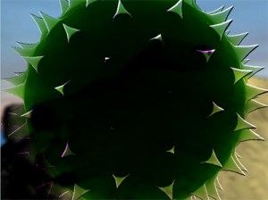
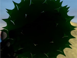
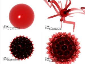
Here are a few other transmitters rendered with this shader:
NOTE:
You might have noticed that I have not used effect.commitChanges(); in this code. If you are rendering many objects using this shader, you should add this code in the pass.Begin() part so the changed will get affected in the current pass, and not in the next pass. This should be done if you set any shader paramteres inside the pass.
Thats if for now. In the next tutorial we will add reflection to the transmitter.
Any feedback is very welcome!
Other ways of doing this
1: As very simple solution to the depth buffer issue,
Martin Evans have supplied me a source code that uses 4 depth render targets to get the depth.
The soruce code is based on this tutorial but addes this feature.
As I promised you, I will write a tutorial that covers this in depth, but this gives you an idea on how to solve it.
Basically, what he is doing, is to first render the two depth buffers as I do it in this tutorial( Using CompareFunction.LessEqual ), but in addition, Martin is making two new depth render targets, but instead of LessEqual, he uses GreaterEqual to calculate a new distance( from behind ) and adding this to the objects depth.
The source can be found here: Executable + Source
2: Matthew Vitelli provided me with another approach to this technique.
What he is doing is to compute the transmission specially for each object. This would allow you to have specialized Du and C components for each object and also reduces the memory usage on the GPU, as well as the pixel overdraw which comes from computing transmission as a fullscreen quad. He has modified the 2-layer transmission approach to include these features. Now, only three render-targets are created in total (1 for near-back face depth, the other 2 for far depth) and each are of half-single (16-bit) precision. The position reconstruction technique works excellently with this. Also, the benefit of doing transmission outside of a post-process lets you have specialized parameters for each object.
Thanks to both of you for adding this!