XNA Workshop at NITH

The workshop I had at NITH yesterday went great. We mananged to talk about cel shading and how different algorithm for impelmenting this can be implemented. I aslo gave them the source-code from my Shader Programming Tutorial 7( written for the workshop really ).
 
So, now it’s all about implementing it into their own engine and see how the game looks from a non-photorealistic perspective!
Posted in General | Leave a comment

Dream-build-play 2009

I just read on the XNA creators forum that there will be an other Dream-Build-Play (http://www.dreambuildplay.com). This is a huge competition where over 350 games competed for $70.000. Now, thats a good reason to start playing around with XNA right?
 
See XNA GDC 2009 – Media Blast for more information.
 
 
Posted in Game programming | 2 Comments

XNA Shader Programming – Tutorial 6, Shader demo

XNA Shader Programming
Tutorial 6 – Shader demo
 
 
Welcome back to my tutorial. Today, we are not going to learn anything new( almost ), but just put together a scene that uses some different shaders in order to see how powerfull shaders can be.
 
I was not sure if I wanted to release the source code for this. The scene/code is hacked together really fast so don’t follow the source code too closely, but rather focus on the shaders. Alot can be made better performance wise, but if proves the point.
 
To move around, use the sticks on the controller. To turn shaders off or on, press A/X.
 
To run this scene, you will need the XBox360 controlles connected to the USB port, or just edit the code so you can move the camera with the keyboard instead.
 
 
The skysphere
This scene uses a simple sphere as a skysphere, slowly rotating to make the scene look alive. To make this even better, one can add more skyes on a different sphere and rotate it in a different speed to get the illution of a more real sky.
 
 
The island
The island is a 3D model created by a friend of mine, Espen Nordahl. The island use a normal map and the same shader covered in tutorial 4, to make the model look more detailed.
 
 
The ocean
The ocean is a plane built up by many vertexes. We use the technique described in tutorial 5( Deform shader ) to create the ocean waves, and using normal map from tutorial 4 to make tinier waves on top of this. I added two normal maps moving in different directions to make the small detail waves ripple on the waves:
Normal = (Normal + Normal2)/2;
 
Here I take the two normals, adding them together and using the avg. of these normals when calculating lighting, diffuse and specular( Tutorial 3 ).
 
I also move the texture coordinates on the color map, making it look like there is some stream in the water.
 
NOTE:
You might have noticed that I have not used effect.commitChanges(); in this code. If you are rendering many objects using this shader, you should add this code in the pass.Begin() part so the changed will get affected in the current pass, and not in the next pass. This should be done if you set any shader paramteres inside the pass.


Posted in XNA Shader Tutorial | 11 Comments

XNA Shader Programming – Tutorial 5, Deform shader

XNA Shader Programming
Tutorial 5 – Deform shader
 
Welcome back to the XNA Shader Programming series. Since the start of tutorial 1, we have been looking at different lighting algorithms. Todays tutorial will be quite short and different, compared to those others, a pure vertex shader effect for deforming objects.
Before we start
In this tutorial, you will need some basic knowledge of shaderprogramming, a understanding of geometry, vector math and matrix math.
 
Deforming objects
Since vertex shaders can be used to process and transform vertices on a per vertex basis, it’s quite ideal to use them to deform objects/meshes. Vertex shaders make it really easy to deform objects, let’s take an example. Say you have a game that will make it possible to create your own character. This includes changing skin color, eye color, hair, clothes and so on. We can in this example create a vertex shader to create a weight property for our character, where say 0 means that our character will be very slim, and 1 that says that our character will be fat.
 
Fat/Slim
To do this, we need a vertex shader that simply moves a vertex along it’s normal:
 
If we move all the vertices along their normals, the object will be bigger, or smaller.
 
 
Ocean waves
Instead of making a big bone animated mesh to create a realistic looking ocean in your game, you could use a vertex shader to produce waves.
To do this, you will need a big flat mesh that will represent your ocean without any waves. You could either do this in 3Ds, or produce it with code. It will need many vertexes, as the shader will move them up and down according to a sine/cos function.
 
 
As we can see in this picture, we got a plane defined by alot of vertexes. We can here use a Vertex Shader to move all vertexes by its Y-axis with a sine function, say
f(y)=sin(y). Say vertex X is moved with pos.Y = sin(X.pos+time);
This will produce waves on the ocean. Ofcourse, this is really simple and pretty ugly. There is alot of differen Ocean algorithms out there, so if you want to look more closely on this subject, just do a google on the topic.
 
To make the ocean look better, you could apply a normal map to create small bumps on the surface, in addition to huge waves. You can also mix sine and cos functions to make more realistic waves.
 
"Fake Spherical harmonics"
This is what I’m going to implement today. Its pretty much a combination of the slim/fat algorithm and the ocean algorithm. The example will use a sphere object, and apply a pretty advanced sin/cos function to move vertexes along their normal in order to deform it, based on time.
 
 
Implementing the shader
The shader is just a Vertex Shader. The pixel shader will only do some basic lighting to make it look more real. You can add normal-mapping here and so on to create really cool looking effects( refer to my last tutorial, 4 ).
In this shader, we will need a time variable, so we can move our vertexes along with a timer to make it look animated, and then we only make a huge mess of sine and cos functions to make it look cool. Feel free to play with these values.
Here is the Vertex Shader for this effect:
 
float4 g_fTime;
 

OUT VS(float4 Pos : POSITION, float3 N : NORMAL)
{
   
    OUT Out = (OUT)0;     
  
   
    float angle=(g_fTime%360)*2;
    float freqx = 1.0f+sin(g_fTime)*4.0f;
    float freqy = 1.0f+sin(g_fTime*1.3f)*4.0f;
    float freqz = 1.0f+sin(g_fTime*1.1f)*4.0f;
    float amp = 1.0f+sin(g_fTime*1.4)*30.0f;
   
    float f = sin(N.x*freqx + g_fTime) * sin(N.y*freqy + g_fTime) * sin(N.z*freqz + g_fTime);
    Pos.z += N.z * amp * f;
    Pos.x += N.x * amp * f;
    Pos.y += N.y * amp * f;
   
    Out.Pos = mul(Pos, matWorldViewProj); 
    Out.N = mul(N, matWorld);    
   
    float4 PosWorld = mul(Pos, matWorld); 
   
    Out.L = vecLightDir;
    Out.V = vecEye – PosWorld;
   
   return Out;
}

This shader calculates an amplitude and a frequency in order to find a smooth value that the vertex can be moved to, based on its vertex.
 

Using the shader
Nothing new here. We only pass a variable time to our shader trough the g_fTime parameter defined in our shader file.

NOTE:
You might have noticed that I have not used effect.commitChanges(); in this code. If you are rendering many objects using this shader, you should add this code in the pass.Begin() part so the changed will get affected in the current pass, and not in the next pass. This should be done if you set any shader paramteres inside the pass.

YouTube – XNA Shader programming, Tutorial 5 – Deform mesh
  

Posted in XNA Shader Tutorial | 6 Comments

XNA Shader Programming – Tutorial 4, Normal mapping

XNA Shader Programming
Tutorial 4 – Normal mapping
 
Welcome back to the XNA Shader Programming series. I hope you enjoyed the last 3 tutorials, and have started to get a grip on shaders!
Last time we talked about Specular lighting, and how to implement this in our own engines. Today I’m going to take this to the next level, and implement Normal Mapping.
 
Before we start
In this tutorial, you will need some basic knowledge of shaderprogramming, vector math and matrix math. Also, the project is for XNA 3.0 and Visual Studio 2008.
 
 
Normal Mapping
Normal mapping is a way to make a low-poly object look like a high-poly objekt, without having to add more polygons to the model. We can make surfaces, like walls, look alot more detailes and realistic by using the technique in todays lesson.
A easy way to descibe normal mapping is that it is used to fake the existence of geometry.
To compute normal mapping, we will need two textures: one for the colormap, like a stone texture, and a normal map that describes the direction of a normal. Instead of calculating the Light by using Vertex normals, we calculate lighting by using the normals stored in the normal map.


Sounds easy, ey? Well, there is one more thing. In most Normal mapping techniques( like the one I’m describing today ), the the normals are stored in something that is called texture space coordinate system, or tangent space coordinate system,. Since the light vector is handled in object or world space, we need to transform the light vector into the same space as the normals in the normalmap.
Tangent space
To describe tangent space, take a look at this image: 
 
Our shader will create a vector W for the texture space coordinate system by using the normal. Then we will calculate U with the help of a DirectX Util function called D3DXComputeTangent() and then calculate vector V by taking the corss-product of W and U.
V = WxU.
Lets take a closer look on how to implement this later, for now, let’s focus on todays next thing: Textures!
As you might have noticed, we need textures to implement normal mapping. Two textures to be spesific.
 
So, how do we load textures? In XNA this is very simple, and I’ll cover this later. And guess what? It’s just as simple to implement textures in our shaders.
To implement textures, we need to create something that is called Texture samplers. A texture sampler, as the name describes, sets the sampler state on a texture. This could be info about how the texture should use filtering( trilinear in our case ), and how the U,V coordinates of the texturemap will behave. This can be clamping the texture, mirroring the texture and so on.
To create a sampler for our texture, we first need to define a texture variable the sampler will use:
texture ColorMap;
 
We can now use ColorMap to create a texture sampler:
sampler ColorMapSampler = sampler_state
{
   Texture = <ColorMap>; // sets our sampler to use ColorMap
   MinFilter = Linear;        // enabled trilinear filtering for this texture
   MagFilter = Linear;
   MipFilter = Linear;  
   AddressU  = Clamp;       // sets our texture to clamp
   AddressV  = Clamp;
};
 
So, we got a texture and a sampler for this texture.
Before we can start using the texture in our shaders, we need to set a sampler stage in our technique:
technique NormalMapping
{
    pass P0
    {
        Sampler[0] = (ColorMapSampler);        
        VertexShader = compile vs_1_1 VS();
        PixelShader  = compile ps_2_0 PS();
    }
}
 
Ok, now we are ready to use our texture!
Since we are using a pixels shader to map a texture to an object, we can simply create a vector named color:
float4 Color;
 
and set the values in the color variable to equal the color in our texture at texturecoordinate UV.
In HLSL, this can easily be done by using a HLSL function called tex2D( s, t ); where s is the sampler, and t is the texture coordinate of the pixel we are currently working on.
Color = tex2D( ColorMapSampler, Tex ); // Tex is an input to our pixel shader, from our vertex shader. It is the texture coordinate our PS is currently working on.
 
Texture coordinates?? Well, let me explain that. A texture coordinate is simpla a 2D coordinate ( U,V ) that is store in our 3D model or object. It is used to map a texture onto the object and are ranging from 0 to 1. 
 
With texture coordinates, the model can have textures assigned to different places, say an Iris texture on the eyeball part of a human-model, or a mouth somewhere in a human face.
As for the lighting algortihm, we will use Specular lighting.
 
Ok, guess we are done with the teory, hope you got an overview of the different components needed in the Normal Map shader.
 
 
Implementing the shader
The biggest differences on this shader and the specular lighting shader is that we will use tangent space instead of object space, and that the normals used for lighting calculation will be retrived from a normal map.
 
First of all, we need to create a new vertex definition that contains Tanges. Add the following piece of code in the top, inside the namespace:
public struct VertexPositionNormalTextureTangentBinormal
{
    public Vector3 Position;
    public Vector3 Normal;
    public Vector2 TextureCoordinate;
    public Vector3 Tangent;
    public Vector3 Binormal;
    public static readonly VertexElement[] VertexElements =
    new VertexElement[]
    {
        new VertexElement(0, 0, VertexElementFormat.Vector3, VertexElementMethod.Default, VertexElementUsage.Position, 0),
        new VertexElement(0, sizeof(float) * 3, VertexElementFormat.Vector3, VertexElementMethod.Default, VertexElementUsage.Normal, 0),
        new VertexElement(0, sizeof(float) * 6, VertexElementFormat.Vector2, VertexElementMethod.Default, VertexElementUsage.TextureCoordinate, 0),
        new VertexElement(0, sizeof(float) * 8, VertexElementFormat.Vector3, VertexElementMethod.Default, VertexElementUsage.Tangent, 0),
        new VertexElement(0, sizeof(float) * 11, VertexElementFormat.Vector3, VertexElementMethod.Default, VertexElementUsage.Binormal, 0),
    };
    public VertexPositionNormalTextureTangentBinormal(Vector3 position, Vector3 normal, Vector2 textureCoordinate, Vector3 tangent, Vector3 binormal)
    {
        Position = position;
        Normal = normal;
        TextureCoordinate = textureCoordinate;
        Tangent = tangent;
        Binormal = binormal;
    }
    public static int SizeInBytes { get { return sizeof(float) * 14; } }
}
 
and then you must tell the graphics device that we want to use our newly created vertex definition. Add this line of code inside the Initialize method:

graphics.GraphicsDevice.VertexDeclaration = new VertexDeclaration(graphics.GraphicsDevice, VertexPositionNormalTextureTangentBinormal.VertexElements);

 
Now on to the shader.. we start by declaring a few global variables:
float4x4 matWorldViewProj;   
float4x4 matWorld;   
float4 vecLightDir;
float4 vecEye;

Nothing new here, lets continue by creating an instance and a sampler for the color map, and the normal map.

texture ColorMap;
sampler ColorMapSampler = sampler_state
{
   Texture = <ColorMap>;
   MinFilter = Linear;
   MagFilter = Linear;
   MipFilter = Linear;  
   AddressU  = Clamp;
   AddressV  = Clamp;
};
 
texture NormalMap;
sampler NormalMapSampler = sampler_state
{
   Texture = <NormalMap>;
   MinFilter = Linear;
   MagFilter = Linear;
   MipFilter = Linear;  
   AddressU  = Clamp;
   AddressV  = Clamp;
};
 
We create an instance of the ColorMap texture  and a sampler for it. These textures will be set trough a parameter from our main application. As you can se, we are using trilinear filtering for both our texture.
Now, the output structure that the Vertex Shader will return looks just the same as in the specular lighting shader:
struct OUT
{
    float4 Pos  : POSITION;
    float2 Tex : TEXCOORD0;
    float3 Light : TEXCOORD1;
    float3 View : TEXCOORD2;
};
 
Let’s continue with the Vertex Shader. There is a lot of new things here, mostly because we want to calculate the tangent space. Have a look at the code:
OUT VS(float4 Pos : POSITION, float2 Tex : TEXCOORD, float3 N : NORMAL, float3 T : TANGENT, float3 B : BINORMAL)
{
      OUT Out = (OUT)0; 
      Out.Pos = mul(Pos, matWorldViewProj); // transform Position
      // Create tangent space to get normal and light to the same space.
      float3x3 worldToTangentSpace;
      worldToTangentSpace[0] = mul(normalize(T), matWorld);
      worldToTangentSpace[1] = mul(normalize(B), matWorld);
      worldToTangentSpace[2] = mul(normalize(N), matWorld);
      // Just pass textures trough
      Out.Tex = Tex;
      float4 PosWorld = mul(Pos, matWorld);
      // Pass out light and view directions, pre-normalized
      Out.Light = normalize(mul(worldToTangentSpace, vecLightDir));
      Out.View = normalize(mul(worldToTangentSpace, vecEye – PosWorld));
      return Out;
}
 
We start by transforming the position as usually.
Then we create a 3×3 matrix, worldToTangentSpace, that is used to transform from world space to tangent space.
Basically, what we get from this vertex shader is the transformed Position, and a transformed Light and View vector based on the tangent space matrix. This is because, as mentioned earlier, the normal map is stored in tangen space. So to calculate a proper light based on the normal map, we need to do this to have all vectors in the same space.
 
So, now that we have our vectos in the right space, we are ready to implement the pixel shader.
The pixelshader need to get the pixelcolor from the colormap, and the normal from the normal map.
Once this is done, we can calulate the ambient, diffuse and specular lighting based on the normal from our normal map.
 
The code for implementing the pixel shader is pretty much straigth forward, have a look at the code:
float4 PS(float2 Tex: TEXCOORD0, float3 L : TEXCOORD1, float3 V : TEXCOORD2) : COLOR
{
      // Get the color from ColorMapSampler using the texture coordinates in Tex.
      float4 Color = tex2D(ColorMapSampler, Tex);
      // Get the Color of the normal. The color describes the direction of the normal vector
      // and make it range from 0 to 1.
      float3 N = (2.0 * (tex2D(NormalMapSampler, Tex))) – 1.0;
      // diffuse
      float D = saturate(dot(N, L));
      // reflection
      float3 R = normalize(2 * D * N – L);
      // specular
      float S = pow(saturate(dot(R, V)), 2);
      // calculate light (ambient + diffuse + specular)
      const float4 Ambient = float4(0.3, 0.3, 0.3, 1.0);
      return Color*Ambient + Color * D + Color*S;
}
 
There ain’t much new here, except for the N variable and the calculation on specular lighting.
The normal use the same function as getting the pixel color from the colormap: tex2D(s,t);
And, its pretty much the same thing. We need to make sure that the normal can range from -1 and 1 so we multiply the normal with two, and subtract one.
float3 N =(2 * (tex2D(NormalMapSampler, Tex)))- 1.0;
 
And also, to compute how shiny the surface will be( specular lighting ) we can use the alphachannel in our colormap to make it possible for artists to specify how shiny different parts of a texture will be.
 
Finally, we create the technique and initiates the samplers used in this shader.
technique NormalMapping
{
    pass P0
    {
        Sampler[0] = (ColorMapSampler);       
        Sampler[1] = (NormalMapSampler);       
   
        VertexShader = compile vs_1_1 VS();
        PixelShader  = compile ps_2_0 PS();
    }
}
 
Using the shader
Ok, not much new when it comes to using the shader, except for the textures!
To initiate and use textures in XNA we are going to use the built in Texture2D class.
Texture2D colorMap;
Texture2D normalMap;
Now we are ready to initialise the texutres using the Content.Load function. We assume that you have created a normal map and a colormap for your object.colorMap = Content.Load<Texture2D>("stone");
normalMap = Content.Load<Texture2D>("normal");
 
Note for those who want to run this on their XBox360:
When adding the sphere.x file, be sure to go into assets and select: "Generate Tangent Frames" in order to get it working on the XBox360.
 
All that is left is to pass the textures into the shader. This is done exactly the same way as other parameters passed to the shader.
effect.Parameters["ColorMap"].SetValue(colorMap);
effect.Parameters["NormalMap"].SetValue(normalMap);
 
Excersises
1. Play with different colormaps and see how the outcome is.
2. Try different models, like a cube to create a detailed brickwall or a stonewall.
3. Implement a normal map shader, with detailed control for all light values( ambient, diffuse, specualar ) and make it possible to enable or disable different parts of the algorithm( tips: use a boolean to set disabled values to zero ). This could result in a pretty cool and flexible shader for your applications.
 
I hope you now understand how normal mapping is implemented, but if not, please give me some feedback so I know what part I need to work on.
But, as you can see, to create good looking effects you won’t have to write big and advanced shaders!
 
Next time, I’m going to write a tutorial about deforming objects.
 
 
NOTE:
You might have noticed that I have not used effect.commitChanges(); in this code. If you are rendering many objects using this shader, you should add this code in the pass.Begin() part so the changed will get affected in the current pass, and not in the next pass. This should be done if you set any shader paramteres inside the pass.

YouTube – XNA Shader programming, Tutorial 4 – Normal mapping
 

Posted in XNA Shader Tutorial | 9 Comments

XNA Shader Programming – Tutorial 3, Specular light

XNA Shader Programming
Tutorial 3 – Specular light
Hi, and welcome to Tutorial 3 of my XNA Shader Programming tutorial. Today we are going to implement an other lighting algorithm called Specular Lighting. This algorithm builds on my Ambient and Diffuse lighting tutorials, so if you haven’t been trough them, now is the time. 🙂
 
Before we start:
In this tutorial, you will need some basic knowledge of shaderprogramming, vector math and matrix math. Also, the project is for XNA 2.0 and Visual Studio 2005.
 
Specular lighting
So far, we got a nice lighting model for making a good looking lighting on objects. But, what if we got a blank, polished or shiny object we want to render? Say a metal surface, plastic, glass, bottle and so on.
To simulate this, we need to implement a new vector to our lighting algorithm: The eye vector.
Whats "the eye" vector, you might think? Well, it’s a pretty easy answer to this. It’s the vector that points from our camera position to the camera target.
We already got this vector in our application code:
viewMatrix   = Matrix.CreateLookAt( new Vector3(x, y, zHeight), Vector3.Zero, Vector3.Up );
 
The position of "The eye" is located here:
Vector3(x, y, zHeight)
 
So let’s take this vector, and store it in a variable:
Vector4 vecEye = new Vector4(x, y, zHeight,0);
 
Let’s look more closely about how to use the shader after we have created it.
 
The formula for Specular Lighting is
I=Ai*Ac+Di*Dc*N.L+Si*Sc*(R.V)^n

Where
R=2*(N.L)*N-L
 
As we can see, we got the new Eye vector V, and aslo we got a reflection vector R.
 
To compute the Specular light, we need to take the dot product of R and V and use this in the power of n where n is controlling how "shiny" the object is.
 
Implementing the shader
It’s time to implement the shader.
As you can see, this object looks polished/shiny, only by using the shader we are going to implement!
Pretty cool, ey?
Lets start by declaring a few variables we will need for this shader:
float4x4 matWorldViewProj;   
float4x4 matWorld;   
float4 vecLightDir;
float4 vecEye;
float4 vDiffuseColor;
float4 vSpecularColor;
float4 vAmbient;
 
And then the output structure for our Vertex Shader. The shader will return the transformed position , Light vector, Normal vector and view vector( the Eye vector ) for a given vertex.
 
struct OUT
{
    float4 Pos  : POSITION;
    float3 L : TEXCOORD0;
    float3 N : TEXCOORD1;
    float3 V : TEXCOORD2;
};
 
Not much new in the vertex shader since last time, except for the V vector. V is calculated by subtracting the transformed position from the Eye vector.
Since V is a part of the OUT structure, and we have defined OUT Out, we can calculate V with the following code:
float4 PosWorld = mul(Pos,matWorld);
Out.L = vecEye – PosWorld
 
where vecEye is a vector passed into the shader trough a shader-parameter( The camera position ).
 
OUT VS(float4 Pos : POSITION, float3 N : NORMAL)
{
    OUT Out = (OUT)0;     
   
    Out.Pos = mul(Pos, matWorldViewProj);   
    Out.N = mul(N, matWorld);               
   
    float4 PosWorld = mul(Pos, matWorld);   
   
    Out.L = vecLightDir;
    Out.V = vecEye – PosWorld;
   
   return Out;
 
And then its time to implement the pixelshader. We start with normalizing the Normal, LightDir and ViewDir to make calculations a bit simpler.
The pixelshader will reatun a float4, that represents the finished color, I, of the current pixel, based on the formula for specular lighding described earlier.
Then, we will calculate direction of the diffuse light as we did in Tutorial 2.
 
The new thing in the Pixel Shader for Specular Lighting is to calculate and use a reflectionvector for L by N, and using this vector to compute the specular light.
So, we start with computing the reflectionvector of L by N:
R = 2 * (N.L) * N – L
As we can se, we have already computed the Dotproduct N.L when computing the diffuse light. Lets use this and write the following code:
float3 Reflect = normalize(2 * Diff * Normal – LightDir);
 
Note: We could also use the reflect function that is built in to HLSL instead, taking an incident vector and a normal vector as parameters, returning a reflection vector:
float3 ref =  reflect( L, N );
 
Now, all there is left is to compute the specular light. We know that this is computed by taking the power of the dotproduct of the reflection vecotor and the view vector, by n: (R.V)^n
You can think of n as a factor for how shiny the object will be. The more n is, the less shiny it is, so play with n to get the result you like.
 
As you might have noticed, we are using a new HLSL function pow(a,b). What this does is quite simple, it returns a^b.
float Specular = pow(saturate(dot(Reflect, ViewDir)), 15);
 
 
Phew, we are finally ready to put all this together and compute the final pixelcolor:
return vAmbient + vDiffuseColor * Diff + vSpecularColor * Specular;
 
This formula should no longer be a suprise for anyone, right?
We start by calculating the Ambient and Diffuse light, and add these together. Then we take the specular light color and multiply it with the Specular component we just calculated, and add it with the Ambient and Diffuse color.
 
The pixelshader for this tutorial could look like this:
 
float4 PS(float3 L: TEXCOORD0, float3 N : TEXCOORD1,
            float3 V : TEXCOORD2) : COLOR
{  
    float3 Normal = normalize(N);
    float3 LightDir = normalize(L);
    float3 ViewDir = normalize(V);   
   
    float Diff = saturate(dot(Normal, LightDir));
   
    // R = 2 * (N.L) * N – L
    float3 Reflect = normalize(2 * Diff * Normal – LightDir); 
    float Specular = pow(saturate(dot(Reflect, ViewDir)), 15); // R.V^n
    // I = A + Dcolor * Dintensity * N.L + Scolor * Sintensity * (R.V)n
    return vAmbient + vDiffuseColor * Diff + vSpecularColor * Specular;
}
 
And offcourse, we have to specify a technique for this shader, and compile the Vertex and Pixel shader:
technique SpecularLight
{
    pass P0
    {
        // compile shaders
        VertexShader = compile vs_1_1 VS();
        PixelShader  = compile ps_2_0 PS();
    }
}
 
The whole code for the shader( .fx ) file is:
float4x4 matWorldViewProj;   
float4x4 matWorld;   
float4 vecLightDir;
float4 vecEye;
float4 vDiffuseColor;
float4 vSpecularColor;
float4 vAmbient;
struct OUT
{
    float4 Pos  : POSITION;
    float3 L : TEXCOORD0;
    float3 N : TEXCOORD1;
    float3 V : TEXCOORD2;
};
OUT VS(float4 Pos : POSITION, float3 N : NORMAL)
{
    OUT Out = (OUT)0;     
   
    Out.Pos = mul(Pos, matWorldViewProj);   
    Out.N = mul(N, matWorld);               
   
    float4 PosWorld = mul(Pos, matWorld);   
   
    Out.L = vecLightDir;
    Out.V = vecEye – PosWorld;
   
   return Out;
}
float4 PS(float3 L: TEXCOORD0, float3 N : TEXCOORD1,
            float3 V : TEXCOORD2) : COLOR
{  
    float3 Normal = normalize(N);
    float3 LightDir = normalize(L);
    float3 ViewDir = normalize(V);   
   
    float Diff = saturate(dot(Normal, LightDir));
   
    // R = 2 * (N.L) * N – L
    float3 Reflect = normalize(2 * Diff * Normal – LightDir); 
    float Specular = pow(saturate(dot(Reflect, ViewDir)), 15); // R.V^n
    // I = A + Dcolor * Dintensity * N.L + Scolor * Sintensity * (R.V)n
    return vAmbient + vDiffuseColor * Diff + vSpecularColor * Specular;
}
technique SpecularLight
{
    pass P0
    {
        // compile shaders
        VertexShader = compile vs_1_1 VS();
        PixelShader  = compile ps_2_0 PS();
    }
}
 
Using the shader
There is almost nothing new when it comes to using the shader in an application since my last tutorial, except for setting the vecEye parameter to the shader.
We just take the position of the camera and pass it to our shader. If you are using a camera-class, there might be a function for getting the camera position. It’s really up to you how you decide to get it.
In my example, i use the same variables for setting the camera position, and creating a vector that is passed to the shader.
 
Vector4 vecEye = new Vector4(x, y, zHeight,0);
and pass it to the shader:
effect.Parameters["vecEye"].SetValue(vecEye);
 
Setting parameters in a shader from the application and how to implement the shader should not be a new topic for you if you’r at this stage, so I won’t go into further detail about this. Please refer to Tutorial 2 and Tutorial 1 about this, or send me an e-mail.
 
We also have to remember to set the technique to "SpecularLight".
 
Excersises
1. Make a new global variable in the shader that specifies the "shininess" of the object. You should be able to set this variable from the application that is using the shader.
2. In this tutorial, you don’t have so much control over the light settings( like setting Ai and Ac, Di and Dc ). Make this shader to support setting Ai, Ac, Di, Dc, Si and Sc where Si and Sc is the color and intensitivity for the specular light
 
Thanks for reading this tutorial, hope I covered it enough for you to understand what this is all about!
If you have any comments, feedback or questions, please ask me on petriw(at)gmail.com.
Next time I’m going to cover Normal mapping, and how to use textures in shaders.
 
NOTE:
You might have noticed that I have not used effect.commitChanges(); in this code. If you are rendering many objects using this shader, you should add this code in the pass.Begin() part so the changed will get affected in the current pass, and not in the next pass. This should be done if you set any shader paramteres inside the pass.
 
Posted in XNA Shader Tutorial | 9 Comments

XNA Shader Programming – Tutorial 2, Diffuse light

XNA Shader Programming
Tutorial 2 – Diffuse light
 
Hi, and welcome to Tutorial 2 of my XNA Shader Programming tutorial. Today we are going to work on Tutorial 1 in order to make the lighting equation a bit more interesting, by implementing Diffuse lighting.
 
Diffuse light
 
Ambient light got the following equation:
I = Aintensity * Acolor
 
Diffuse lighting builds on this equation, adding a directional light to the equation:
I = Aintensity x Acolor + Dintensity x Dcolor x N.L (2.1)
 
From this equating, you can see that we still use the Ambient light, but need two more variables for describing the color and intensity of the Diffuse light, and two vectors N and L for describing the light direction L compared to the surface normal N.
 
We can think of Diffuse lighting as a value that indicates how much a surface reflects light. The light that is reflected will be stronger and more visible when the angle between the Normal N and the light direction L gets smaller and smaller.
 
 
If L is parallel with N, the light will be strongest reflected, and if L is parallel with the surface, the light will be reflected with the minimal amount.
 
To compute the angle between L and N, we can use the Dot-product, or the scalar product. This rule is used to find the angle between two given vectors and can be defines as the following:
N.L = |N| x |L| x cos(a)      where |N| is the length of vector N, |L| is the length of vector L and cos(a) is the angle between the two vectors.
 
Implementing the shader
We need three global variables:
 
float4x4    matWorldViewProj;
float4x4    matWorld;
float4      vLightDirection;
 
We still have the worldviewprojection matrix from tutorial one, but in addition, we have the matWorld matrix that is used to calculate a correct normal related to the world matrix, and a light direction vLightDirection that explains what direction that light have.
 
We also need to define the OUT structure for our vertex shader, in order to make the correct light equation in the pixel shader:
struct OUT
{
    float4 Pos: POSITION;
    float3 L:    TEXCOORD0;
    float3 N:    TEXCOORD1;
};
 
Here we have the position Pos, the light direction L and the Normal N stored in different registers. TEXCOORDn can be used for any values, and as we don’t yet use any texture coordinates, we can easily just use these registers as a storage for our two vectors.
 
Ok, its time for our vertex shader:
OUT VertexShader( float4 Pos: POSITION, float3 N: NORMAL )
{
    OUT Out = (OUT) 0;
    Out.Pos = mul(Pos, matWorldViewProj);
    Out.L = normalize(vLightDirection);
    Out.N = normalize(mul(N, matWorld));
    return Out;
}
 
We take the position from the model file, as well as the normal, and pass it into the shader. Based on these and our global variables, we can transform the position Pos, normalize the light direction and transforming+normalizing the normal of the surface.
 
Then, in the pixel shader we take the values in TEXCOORD0 and put it in L, and the values in TEXCOORD1 and put it in N. These registers are filled by the vertex shader. Then we implement equation 2.1 in the pixel shader:
 
float4 PixelShader(float3 L: TEXCOORD0, float3 N: TEXCOORD1) : COLOR
{   
    float Ai = 0.8f;
    float4 Ac = float4(0.075, 0.075, 0.2, 1.0);
    float Di = 1.0f;
    float4 Dc = float4(1.0, 1.0, 1.0, 1.0);
    return Ai * Ac + Di * Dc * saturate(dot(L, N));
}
 
 
The technique for this shader is the following:
technique DiffuseLight
{
    pass P0
    {
        VertexShader = compile vs_1_1 VertexShader();
        PixelShader = compile ps_1_1 PixelShader();
    }
}
 
 
Ok, thats if for Diffuse light! Download the source and play around with it in order to understand it fully 🙂 I hope that you start to see the power of shaders now and how to use them in your own application!
 
NOTE:
You might have noticed that I have not used effect.commitChanges(); in this code. If you are rendering many objects using this shader, you should add this code in the pass.Begin() part so the changed will get affected in the current pass, and not in the next pass. This should be done if you set any shader paramteres inside the pass.
Posted in XNA Shader Tutorial | 9 Comments

XNA Shader Programming – Tutorial 1, Ambient light

XNA Shader Programming
Tutorial 1 – Ambient light
Hi, and welcome to tutorial 1 of my XNA Shader Tutorial series.
My name is Petri Wilhelmsen and is a member of Dark Codex Studios. We usually participate in various competitions regarding graphics/game development, at The Gathering, Assembly, Solskogen, Dream-Build-Play, NGA and so on.
 
The XNA Shader Programming series will cover many different aspects of XNA, and how to write HLSL shaders using XNA and your GPU. I will start with some basic theory, and then move over to a more practical approach to shader programming.
The theory part will not be very detailed, but should be enough for you to get started with Shaders and be able to experiment for yourself. It will cover the basics around HLSL, how the HLSL language works and some keywords that is worth knowing about.
 
Today I will cover XNA and HLSL, as well as a simple ambient lighting algorithm.
 
Prerequisites
Some programming in XNA, as I wont go much into details about loading textures, 3d models, matrices and some math.
 
A short history about shaders
Before DirectX8, GPU’s had a fixed way to transform pixels and vertices, called "The fixed pipeline". This made it impossible to developers to change how pixels and vertices was transformed and processed after passing them to the GPU, and made games look quite similar graphics wise.
DirectX8 introduced the vertex and pixel shaders, that were a method developers could use to decide how the vertices and pixles should be processed when going through the pipeline, giving them a lot of flexibility.
An assembly language was used to program the shaders, something that made it pretty hard to be a shader developers, and shader model 1.0 was the only supported version. But this changed once DirectX9 was released, giving developers the opportunity to develop shaders in a high level language, called High Level Shading Language( HLSL ), replacing the assmely shading language with something that looked more like the C-language. This made shaders much easier to write, read and learn.
DirectX10.0 introduced a new shader, the Geometry Shader, and was a part of Shader Model 4.0. But this required a new state-of-the-art graphics card, and Windows Vista.
XNA supports Shader Model 1.0 to 3.0, but works on XP, Vista and XBox360!
 
Shaders?
Well, enough history.. Really, what is a shader?
As I said, shaders can be used to customize steps in the pipeline to make it up to the developer to implement how pixels/vertices should be processed.
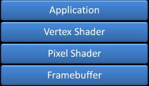
As we can see from the figure below, an application got initiates and uses a shader when rendering, the vertex buffer works with the pixelshader by sending required data from the vertex shader to the pixel shader, working together to create an image to the framebuffer.
 
One important fact to note behind your ears is that many GPUs does not support all shader models. This should be accounted for when developing shaders. One shader should have alternate methods to archive similar/simpler effects, making the application work on older computers.
 
Vertex Shaders
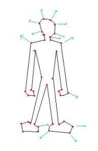
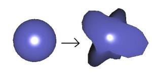
Vertex shaders is used to manipulate vertex-data, per vertex. This can for example be a shader that makes a model “fatter” during rendering by moving vertexes along their normals to a new position for every vertex in the model( deform shaders ).
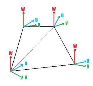
Vertex shaders got input from a vertex structure defines in the application code, and loads this from the vertex buffer, passed into the shader. This describes what properties each vertex will have during shading: Position, Color, Normal, Tangent++.
The vertex shader sends its output to for later use in the pixel shader. Do define what data the vertex shader will pass to the next stage can be done by defining a struct in the shader, containing the data you want to store, and make the vertex shader return this instance, or by defining parameters in the shader, using the out keyword. Output can be Position, Fog, Color, Texture coordinates, Tangets, Light position and so on.
 
struct VS_OUTPUT
{
    float4 Pos: POSITION;
};
VS_OUTPUT VS( float4 Pos: POSITION )
{
    VS_OUTPUT Out = (VS_OUTPUT) 0;
    …
    return Out;
}
// or
float3 VS(out float2 tex : TEXCOORD0) : POSITION
{
      tex = float2(1.0, 1.0);
      return float3(0.0, 1.0, 0.0);
}
 
Pixel Shaders
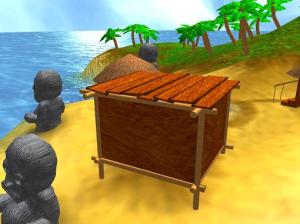
The Pixel shader manipulates all pixels( per pixel ) on a given model/object/collection of vertices. This can be a metal box, where we want to customize the lighting algorithm on, colors and so on. The pixel shader gets data from the vertex shaders output values, like position, normals and texture coordinates:
 
float4 PS(float vPos : VPOS, float2 tex : TEXCOORD0) : COLOR
{
      …
      return float4(1.0f, 0.3f, 0.7f, 1.0f);
}
 
The pixel shader can have two output values, Color and Depth.
 
 
HLSL
High Level Shading Language is used to develop shaders. In HLSL, you can declare variables, functions, datatypes, testing( if/else/for/do/while+) and much more, in order to create a logic for vertices and pixels. Below is a table of some keywords that exists in HLSL. This is not all of them, but some of the most important ones.
 
Examples of datatypes in HSLS
bool true or false
int 32-bit integer
half 16bit integer
float 32bit float
double 64bit double
 
Examples of vectors in HSLS
float3 vectorTest
float vectorTest[3]
vector vectorTest
float2 vectorTest
bool3 vectorTest
 
Matrices in HSLS
float3x3: a 3×3 matrix, type float
float2x2: a 2×2 matrix, type float
 
We also have a lot of helper functions in HSLS, which help us archive complex mathematical expressions.
cos( x ) Returns cosine of x
sin( x) Returns sinus of x
cross( a, b ) Returns the cross product of two vectors a and b
dot( a,b ) Returns the dot product of two vectors a and b
normalize( v ) Returns a normalized vector v ( v / |v| )
 
 
HSLS offers a huge set of functions just waiting for you to use! Learn them, so you know how to solve different problems.
 
Effect files
Effect files ( .fx ) makes shader developing in HSLS easier, and you can store almost everything regarding shaders in a .fx file. This includes global variables, functions, structures, vertex shader, pixel shader, different techniques/passes, textures and so on.
We have already seen how to declare variables and structures in a shader, but what is this technique/passes thing?  It’s pretty simple. One Shader can have one or more techniques. Each technique can have a unique name and from the game/application, we can select what technique in the shader we want to used, by setting the CurrentTechnique property of the Effect class.
effect.CurrentTechnique = effect.Techniques["AmbientLight"];
 
Here, we set “effect” to use the technique “AmbientLight”. One technique can have one or more passes, and we must remember to process all passes in order to archive the result we want.
This is an example of a shader containing one technique and one pass:
technique Shader
{
    pass P0
    {
        VertexShader = compile vs_1_1 VS();
        PixelShader = compile ps_1_1 PS();
    }
}
 
This is an example of a shader containing one technique and two passes:
technique Shader
{
    pass P0
    {
        VertexShader = compile vs_1_1 VS();
        PixelShader = compile ps_1_1 PS();
    }
pass P1
    {
        VertexShader = compile vs_1_1 VS_Other();
        PixelShader = compile ps_1_1 PS_Other();
    }
}
 
This is an example of a shader containing two techniques and one pass:
technique Shader_11
{
    pass P0
    {
        VertexShader = compile vs_1_1 VS();
        PixelShader = compile ps_1_1 PS();
    }
}
technique Shader_2a
{
    pass P0
    {
        VertexShader = compile vs_1_1 VS2();
        PixelShader = compile ps_2_a PS2();
    }
}
We can see that a technique got two functions, one for the pixel shader and one for the vertex shader.
VertexShader = compile vs_1_1 VS2();
PixelShader = compile ps_1_1 PS2();
This tells us that the technique will use VS2() as the vertex shader, PS2 as the pixel shader, and will support shader model 1.1 or higher. This makes it possible to have a different and more complex shader for GPUs supporting higher shader model versions.
 
 
Implementing Shaders in XNA
Its really easy to implement shaders in XNA. In fact, only a few lines of code is needed to load and use a shader. Here is a list of steps that can be followed when making a shader:
1. Make the shader
2. Put the shaderfile( .fx ) in “Contents”
3. Make an instance of the Effect class
4. Initiate the instance of the Effect class.
5. Select what technique you want to use
6. Begin the shader
7. Pass different parameters to the shader
8. Draw the scene/object
9. End the shader
 
The steps in a bit more detail:
1.When making a shader, several programs like notepad, visual studio editor and so on can be used. There are also some shader IDEs available, and personally I like to use nVidias FX Composer: http://developer.nvidia.com/object/fx_composer_home.html
 
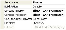
2. When the shader is created, drag it into the ”Content” colder, so it gets an asset name:
 
3. XNA Framework includes a Effect class that is used to load and compile the shaders. To make an instance of this class, write the following line of code:
Effect effect;
Effect is a part of the “Microsoft.Xna.Framework.Graphics” library, so remember to add this line of code to the using statement block:
using Microsoft.Xna.Framework.Graphics
4. To initiate the shader, we can use Content to either load if from the project or from a file:

effect = Content.Load<Effect>("Shader");
Shader is the asset name of the shader you added to the Contents folder.
5. Select what technique you want to use:
effect.CurrentTechnique = effect.Techniques["AmbientLight"];
6. To start using an Effect, call the Begin() function:
effect.Begin();
Also, you must start all the passes in the shader.
foreach (EffectPass pass in effect.CurrentTechnique.Passes)
{
    // Begin current pass
    pass.Begin();
 
7. There are many ways to set a Shader parameter, but the following is sufficient for the tutorial. Note: This is not the fastest way of doing this, and I will come back to this in a later tutorial:
effect.Parameters["matWorldViewProj"].SetValue( worldMatrix * viewMatrix * projMatrix);
where "matWorldViewProj" is defined in the shader: float4x4 matWorldViewProj; and worldMatrix * viewMatrix * projMatrix er is a matrix that matWorldViewProj is set to.
 
SetValue sets a value to the parameter and sends it to the shader, and GetValue<Type> retrives a value from the shader, where Type is the datatype to retrive. For example, GetValueInt32() gets an integer from the shader.
 
8. Render the scene/object you want this shader to process/transform.
 
9. To stop the pass, call pass.End() and to stop the shader, call the End() method of Effect:
pass.End();
effect.End();
To understand this better, open the source code provided and see the steps in action.
Ambient light
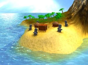
Ok, we are finally at the last step, implementing the shader! Not bad eh?
First of all, what is an "Ambient light"?
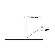
Ambient light is the basic light in a scene that’s just there. If you go into a complete dark room, the ambient light is typically zero, but when walking outside there is almost always some light that makes it possible to see. This light got no direction and is here to make sure objects that are not lit, will have a basic color.
 
The formula for Ambient light is:
I = Aintensity x Acolor ( 1.1)
 
where L is the light, Aintensity is the intensity of the light( usually between 0.0 and 1.0, and Acolor is the color of the ambient light. This color can be a hardcoded value, a parameter or a texture.
 
Ok, lets start implementing the shader. First of all, we need a matrix that represents the world matrix:
float4x4 matWorldViewProj;
 
Declare this in the top of the shader as a global variable.
Then, we need to know what values the vertex shader will pass to the pixel shader. This is done by creating a structure( you can name it to whatever you want):
 
struct OUT
{
    float4 Pos: POSITION;
};
 
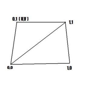
We create a structure named OUT that contains a variable of the type float4 with the name Pos. The :POSITION in the end tells the GPU what register to put this value in. So, what is a register? Well, a register is simply just a container in the GPU that contains data. The GPU got different registers to put position data, normal, texture coordinates and so on, and when defining a variable that the shader will pass to the pixel shader, we must also decide where in the GPU this value is stored.
 
Lets take a look at the vertex shader:
 
OUT VertexShader( float4 Pos: POSITION )
{
    OUT Out = (OUT) 0;
    Out.Pos = mul(Pos, matWorldViewProj);
    return Out;
}
 
We create the vertex shader function of the OUT type, where it takes in the parameter float4 Pos: POSITION. This is the position of the vertex defined in the model file/application/game.
 
Then, we make an instance of the OUT structure name Out. This structure must be filled and returned from the function for later processing.
The position we have in the input parameter is not processed, and needs to be multiplied with the worldviewprojection matrix in order to be placed correctly on the screen.
As this is the only variable in OUT, we are ready to return it and move on.
 
Now, its the pixel shaders turn to make a move. We declare this as a float4 function, returning a float4 value stored in the COLOR register of the GPU.
It’s in the pixel shader we will compute the ambient light algorithm:
float4 PixelShader() : COLOR
{
    float Ai = 0.8f;
    float4 Ac = float4(0.075, 0.075, 0.2, 1.0);
   
    return Ai * Ac;
}
 
Here we use 1.1 to calculate what the color of the current pixel will be. Ai is the ambient intensity, and Ac is the ambient color.
 
Last, we must define the technique and bind the pixelshader and certex shader function to the technique:
technique AmbientLight
{
    pass P0
    {
        VertexShader = compile vs_1_1 VertexShader();
        PixelShader = compile ps_1_1 PixelShader();
    }
}
 
 
Ok, thats it!
Now, i recommend you to look at the source code and play around with the values in order to understand how to setup and implement a shader using XNA.
 
NOTE:
You might have noticed that I have not used effect.commitChanges(); in this code. If you are rendering many objects using this shader, you should add this code in the pass.Begin() part so the changed will get affected in the current pass, and not in the next pass. This should be done if you set any shader paramteres inside the pass.
Download: Executable + Source
 
Posted in XNA Shader Tutorial | 18 Comments

XNA Shader Programming – Tutorial 7, Toon shading

XNA Shader Programming
Tutorial 7 – Toon shading

Hi, and welcome to tutorial 7 of my XNA Shader Tutorial series. Today I will cover a simple algorithm for rendering a non-photorealistic scene using Cel shading/Toon shading, using HLSL and XNA 3.0.
Executable and source-code can be found at the end of this article.
To implement this effect, we need two shaders:
  • (a) The toon shader will add lighting based on a look-up texture, by using the diffuse algorithm covered in XNA Shader Tutorial 2( see gamecamp.no or come to my presentations at NITH, Oslo ).
  • (b) A post process edge detection algorithm.
First of all, we render the scene with the first shader(a) to a render target, and then we use this texture in shader (b) to find the edges and finally combining the edges with the scene:
Shader (a) + (b) results in the final output color.
Cel/Toon shader
To create the cel/toon shading shader we compute the diffuse light ( N dot  L ) and use this as a texture x-coordinate:
Tex.y = 0.0f;
Tex.x = saturate(dot(L, N));
float4 CelColor = tex2D(CelMapSampler, Tex);
where CelMapSampler sampler for a 2D lookup texture(resolution 32×1) looking like this:
if the angle between L and N is large( dot product = 0 ) the texture at coordinate 0.0,0.0 will be used. If the angle between N and L is 0( dot product = 1 ) the pixels at coordinate 1.0,0.0 will be used, and anything inbetween will range from 0.0->1.0. As you can see on the texture, only 3 different colors is used.
By returning the CelColor from the pixel shader, the output will be the diffuse shading using the colors in the lookup texture:
But we want textures as well. This can simply be done in the same way as in Shader Tutorial 2, but instead of using the diffuse color multiplied with the texture color, we can multiply the texture color with the toon-shaded diffuse map CelColor:
return (Ai*Ac*Color)+(Color*Di*CelColor);
The result of this shader will look like this:
Not very hard eh? 🙂
Ok. This looks pretty good and can be used. But in some cases, one might want to have outlines like many drawings have.
– One approach to this is by first rendering the culled version of the object totally black, and then rendering the cel-shaded version of the object, but a tiny bit smaller,
– Another approach is to render the scene to a texture, and applying post process edge detection shader to the scene. This is how we are going to do it in this tutorial.
Post process Edge Detection
The edge detection shader in this shader is a kernel filter with the following matrix:

A kernel filter works by applying a kernel matrix to every pixel in the image. The kernel contains multiplication factors to be applied to the pixel and its neighbors. Once all the values have been multiplied, the pixel is replaced with the sum of the products. By choosing different kernels, different types of filtering can be applied.

Applying this shader to a texture will create a black and white texture, where the edges are black and the rest is white.

This makes it very easy to create combine the normal scene with the edges:

Color*result.xxxx;

Where Color is the scenetexture, and result.xxxx is the edge detection texture.
When multiplying Color with result, all pixels that is not a part of an edge is white(in result ) and is the same as 1.0, and edges is 0.0( black ). Multiplying Color with 1.0 equals color, and multiplying color with the black edges( 0.0 ) will result in a 0.0( black color ).

As you can see, toon-shaders is not very hard and can easily be implemented in any scenes with a few lines of code. If you haven’t yet done so, download the executable files and the source, and start experimenting!

NOTE:
You might have noticed that I have not used effect.commitChanges(); in this code. If you are rendering many objects using this shader, you should add this code in the pass.Begin() part so the changed will get affected in the current pass, and not in the next pass. This should be done if you set any shader paramteres inside the pass.

YouTube – XNA Shader programming, Tutorial 7 – Toon shading
  

Download: Source + Executable
XNA 4.0 version: http://adventureincode.blogspot.com/2011/08/cel-shading-example-in-xna-40.html

Posted in XNA Shader Tutorial | 15 Comments

Project Silvershine to XNA, Cel-shading Workshop

As XNA is a great platform to work with I decided to port the Silvershine project to XNA so it can be played on both XBox360 and PC/Windows.
 
Also, on Monday I’m going to have a workshop on "Cel-shading with XNA" for a team participating( and made it to the semifinals ) in the Imagine Cup 2009 competition. I helped them last year as well and I think it’s great that they continue to work together using the XNA platform.
Posted in Game programming | 2 Comments